Note: xTool Rotary Attachment 3 Lite is an accessory designed exclusively for xTool M2. It is used with xTool M2 to process rotating workpieces.
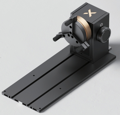
Purchase link: RA3 Lite for M2
Download PDF file (multi-language)
xTool Rotary Attachment 3 Lite (RA3 Lite) Quick Start Guide
Links to the video tutorial and article for using xTool M2 with RA3 Lite
Video
Article: Use xTool Rotary Attachment 3 Lite with xTool M2
Safety precautions
- The product features a magnetic quick-release design. Do not put your hand between magnetic parts during use to avoid pinching yourself. There is also a risk of pinching when assembling different modules, rotating the jaw chuck, and adjusting the power module and the support module.
- Keep the product away from children.
- Clean the product using a dry cloth.
Note: Click here for multi-language safety instructions.
List of items
Unbox xTool Rotary Attachment 3 Lite and check the items inside the pack. If you find items missing or broken, please contact us for after-sales support.
Part name | Image |
|---|---|
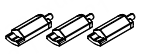
Jaw chuck |
|
Cylindrical jaw |
|
T-shaped jaw |
|
Extended jaw |
|
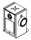
Power module |
|
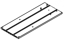
Main baseplate |
|
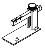
Support module |
|
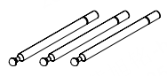
Stud components |
|
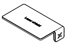
Laser shield |
|
Horizontal laser emission holder |
|
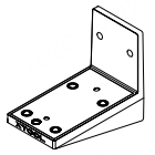
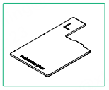
Positioning plate |
|
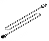
Device connection cable |
|
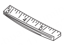
Tape measure |
|
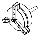
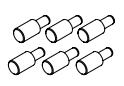
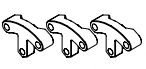

Use xTool Rotary Attachment 3 Lite
Preparations
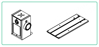
1. Fix the power module on the main baseplate.
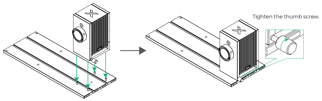
2. Assemble the jaw chuck components.
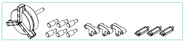
- Method 1: Suitable for processing common rotating workpieces

- Method 2: Suitable for processing large or smooth-surfaced rotating workpieces
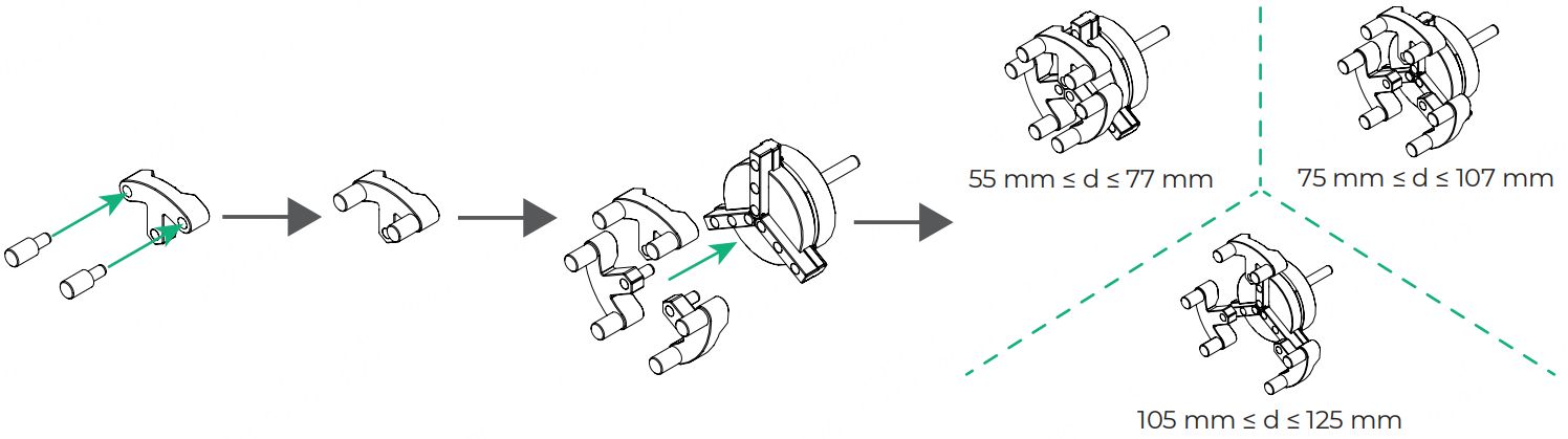
- Method 3: Suitable for processing small or lightweight rotating workpieces

Process cylindrical objects
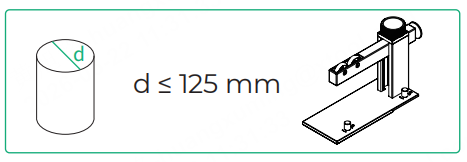
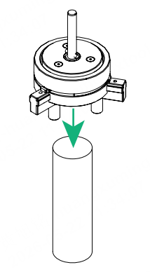
1. Put the workpiece on a table. Place the jaw chuck against the workpiece as illustrated, with its jaws surrounding the outside of the workpiece.
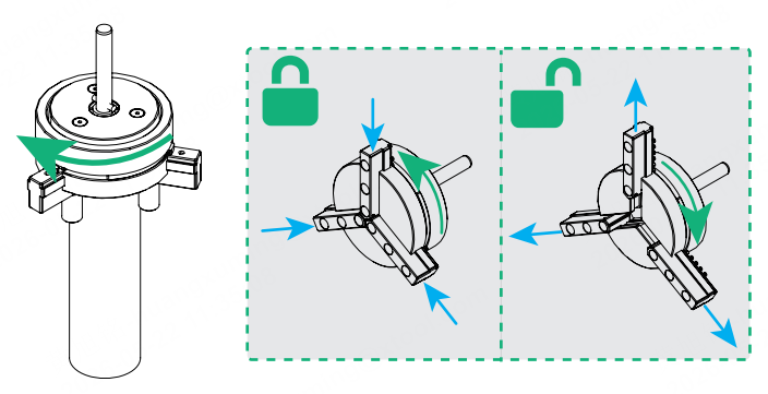
2. Rotate the knob to secure the workpiece.
3. Insert the jaw chuck components into the power module.
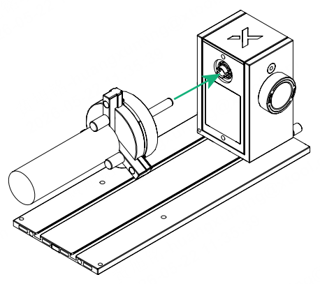
4. Rotate the jaw chuck components until you hear a click.
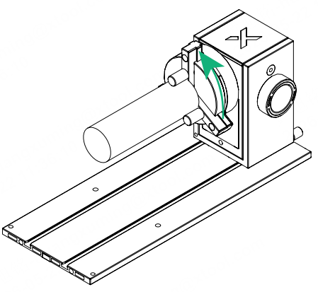
Note: To remove the jaw chuck from the power module, hold the jaw chuck firmly and pull it straight out.
5. Slide the support module into the main baseplate.
Note: If the workpiece diameter is ≤ 55 mm, it is recommended not to install the support module. Otherwise, the laser module may collide with the support module during processing.
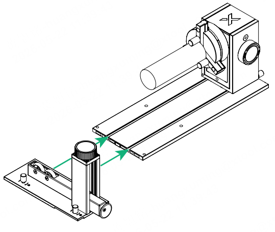
6. Rotate the knob clockwise to hold the support module in position.
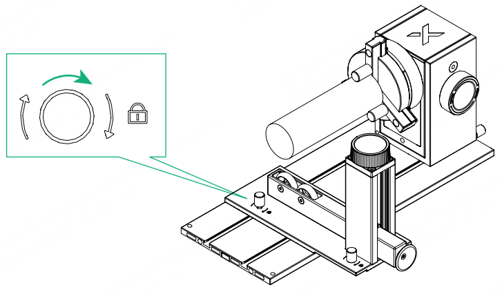
7. Rotate the knob to adjust the height of the two wheels on the support module until they touch the workpiece.
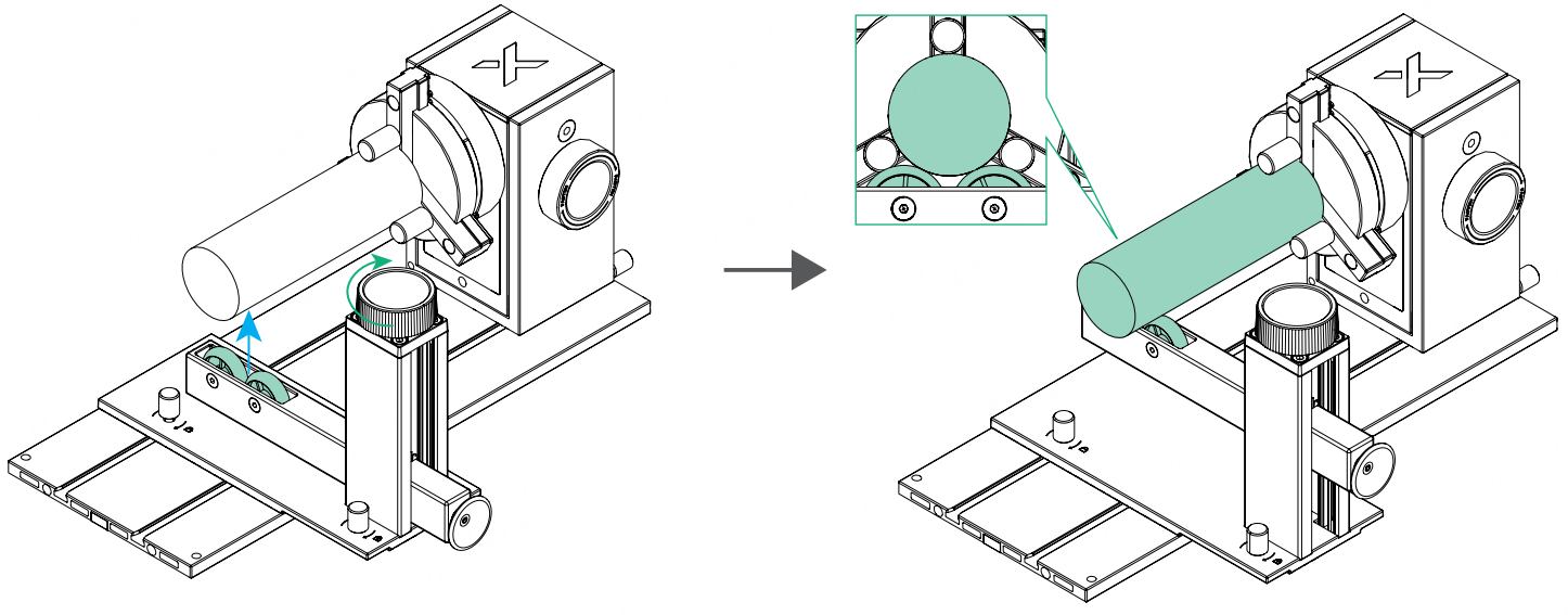
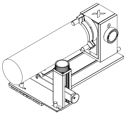
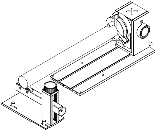
Note: If the workpiece is long, there are two methods to use the support module.
Method 1: Slide the support module into the main baseplate and hold it in position
Method 2: Place the support module outside the main baseplate
The following are common application scenarios for using extended jaws, as well as simultaneously using cylindrical jaws and T-shaped jaws.
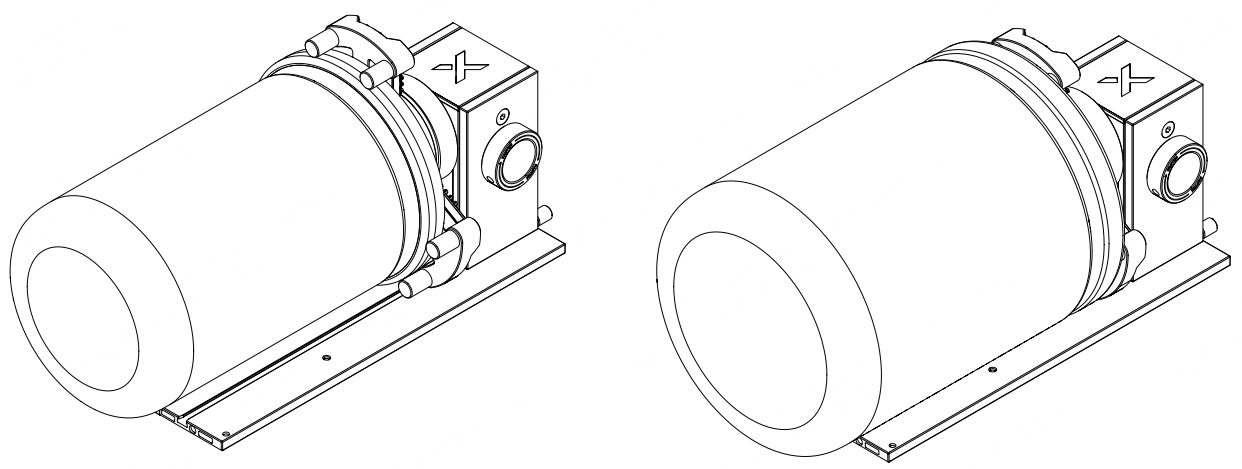
- Extended jaws: Primarily suitable for processing rotating workpieces with a diameter of less than 80 mm. It is recommended to mount the extended jaws in the middle or the innermost holes of the jaw chuck.
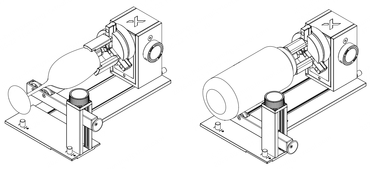
Warning: If other jaws are mounted in the middle or the innermost holes of the jaw chuck, the laser module may collide with the jaw chuck or other components during processing.
- Cylindrical jaws + T-shaped jaws: It is recommended to mount them in the outermost holes of the jaw chuck.
If the workpiece is a mug with a handle, it is recommended to use cylindrical jaws and T-shaped jaws to secure the mug. Refer to the following illustration for the recommended handle placement.
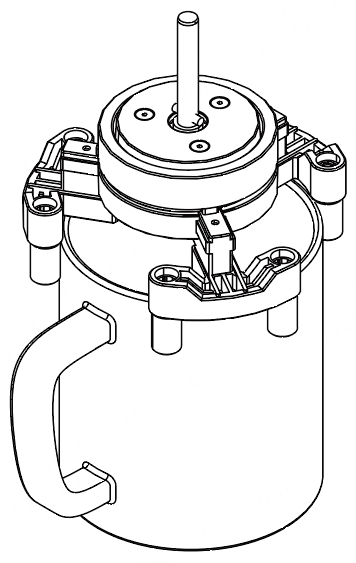
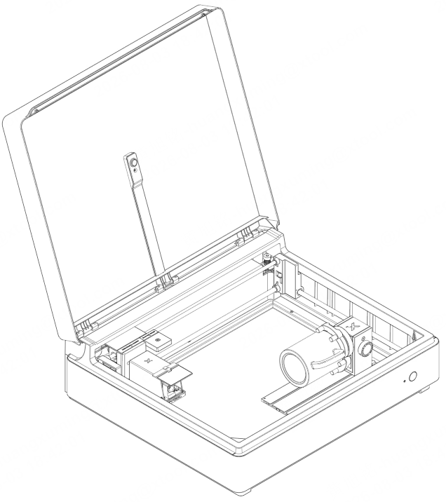
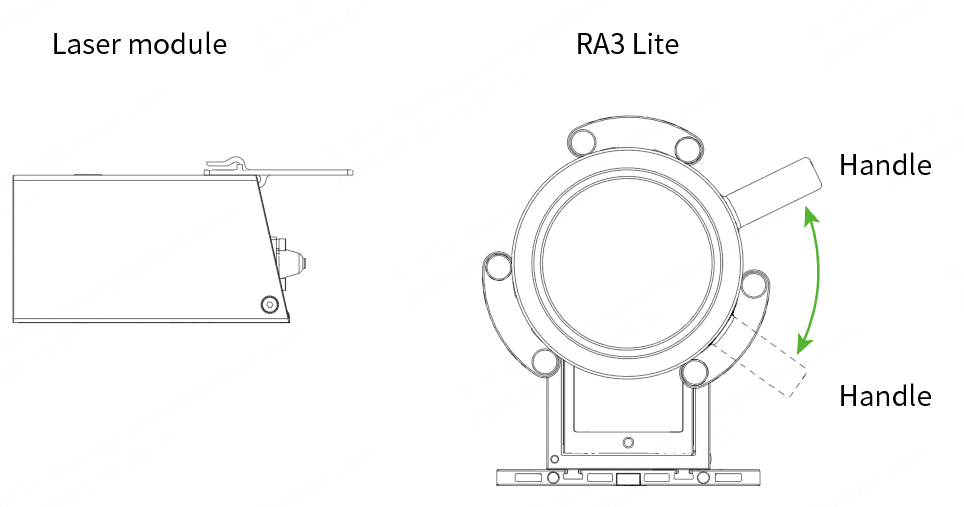
- A handle placed too high may collide with the lid of xTool M2 during processing.
- A handle placed too low may collide with the main baseplate of RA3 Lite during processing.
- An overly long handle may collide with the front plate of xTool M2 where the Start/Stop button is located.
- Before processing, use the Framing function in xTool Studio to check whether the handle interferes with surrounding parts during movement.
Process spherical objects
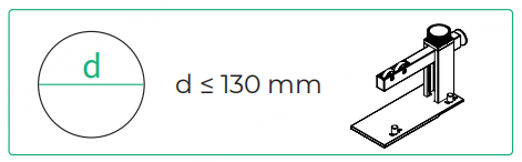
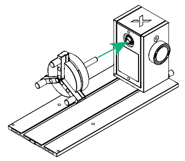
1. Insert the assembled jaw chuck components into the power module.
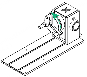
2. Rotate the jaw chuck components until you hear a click.
Note: To remove the jaw chuck from the power module, hold the jaw chuck firmly and pull it straight out.
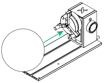
3. Place one side of the workpiece against the jaws.
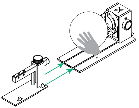
4. Slide the support module into the main baseplate, with its bell mouth against the other side of the workpiece.
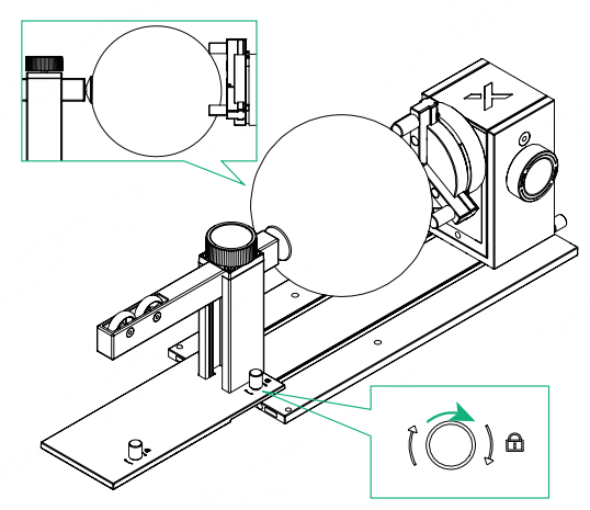
5. Rotate the knob clockwise to hold the support module in position.
Process rings
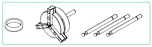
1. Install the stud components.
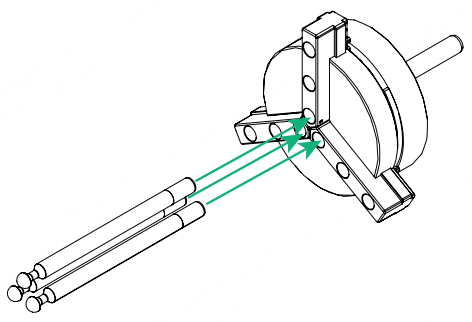
2. Place the ring onto the stud components.
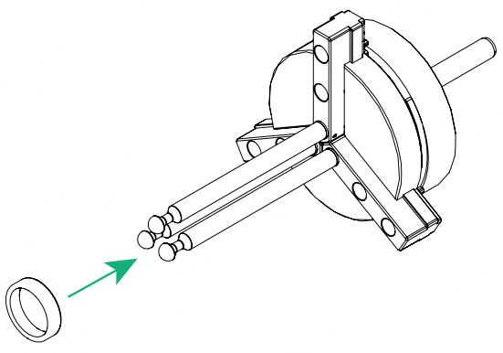
3. Rotate the knob to secure the ring.
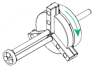
4. Insert the jaw chuck into the power module.
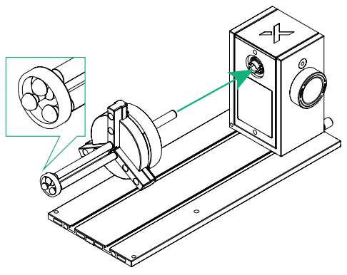
5. Rotate the jaw chuck until you hear a click.
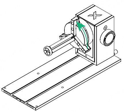
Note: To remove the jaw chuck from the power module, hold the jaw chuck firmly and pull it straight out.
Use with xTool M2
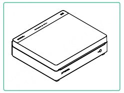
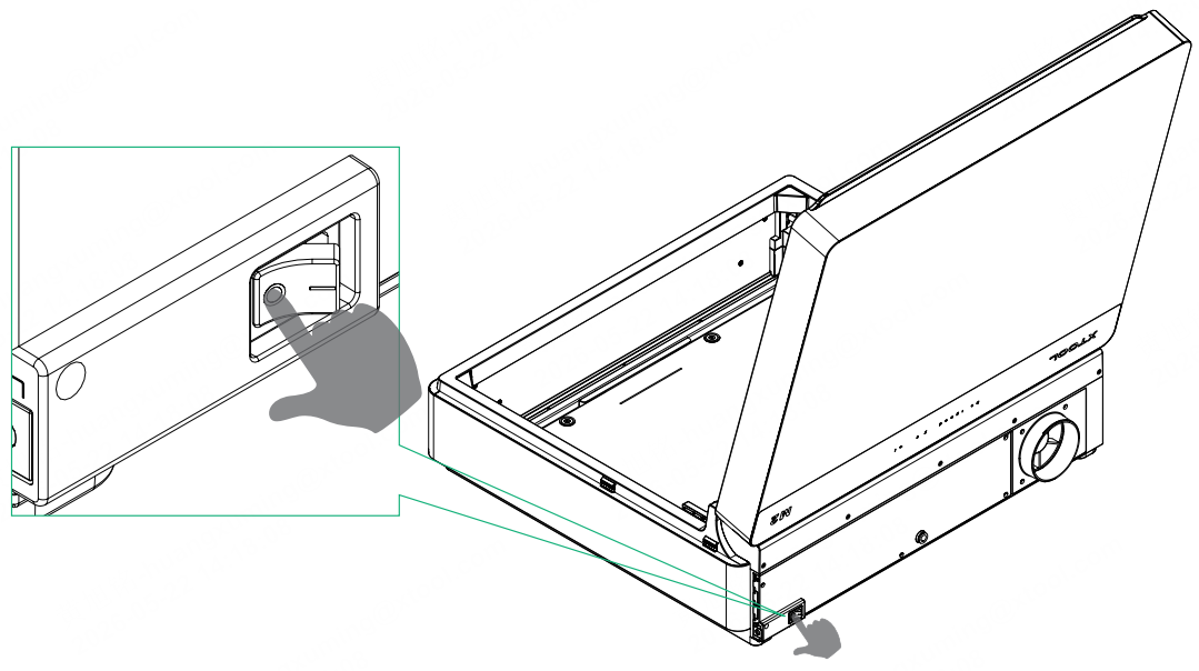
1. Press the power switch of xTool M2 to turn off the device.
2. Remove the module connection cable.
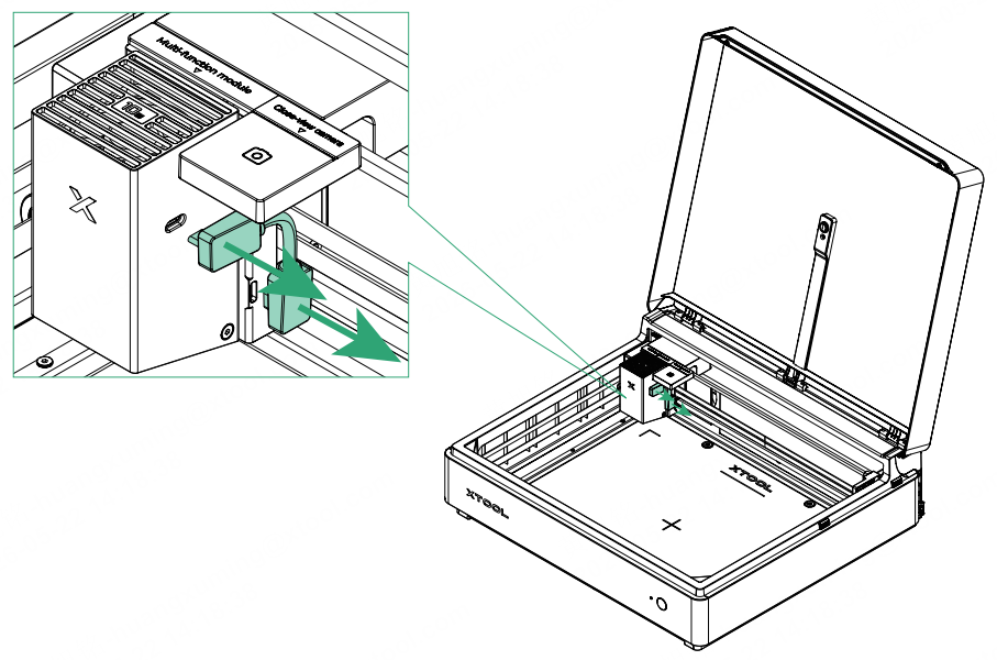
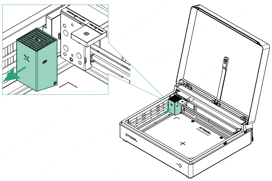
3. Remove the laser module.
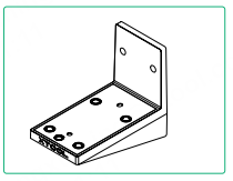
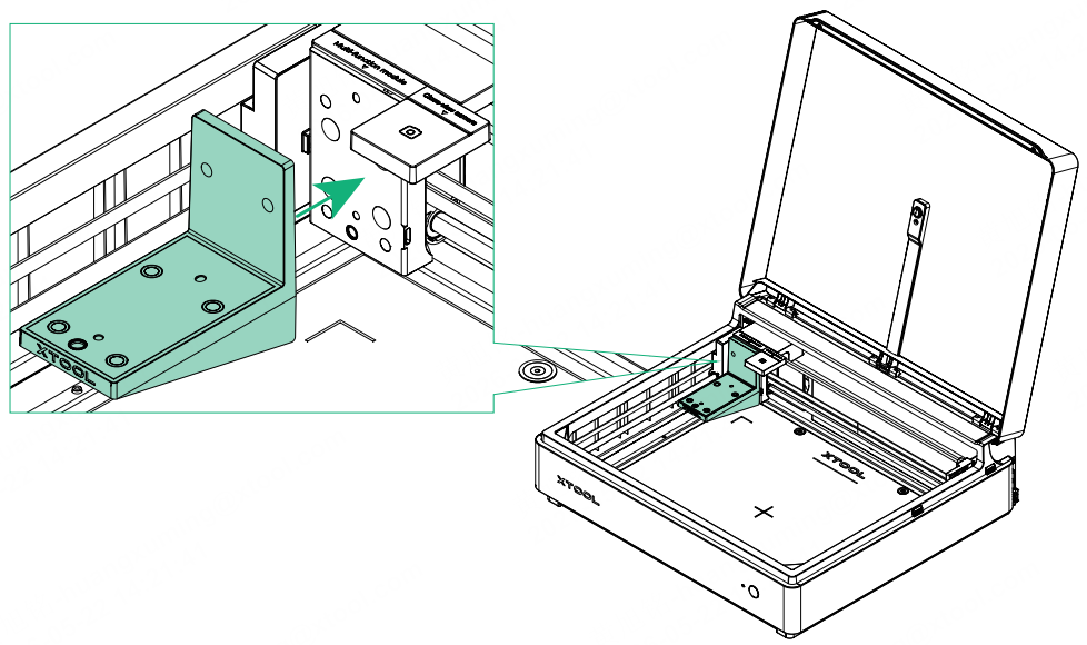
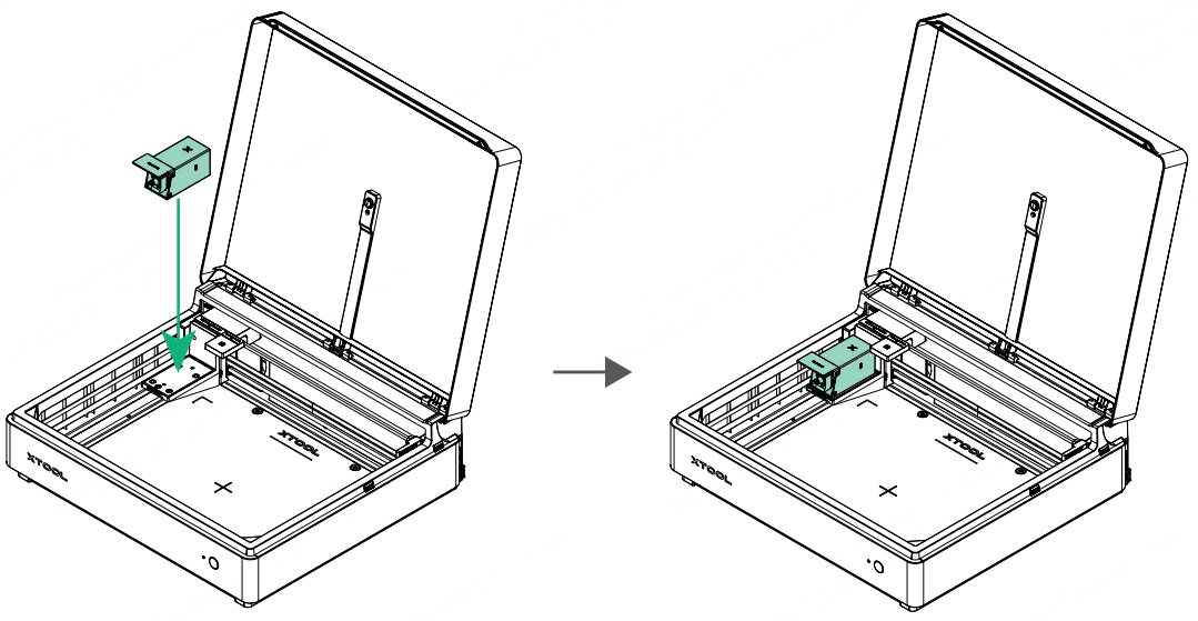
4. Attach the horizontal laser emission holder to the multi-function module holder.
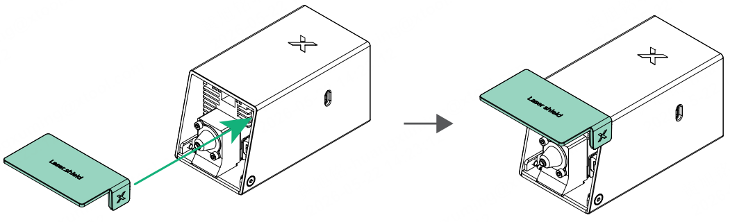
5. Install the laser shield to the laser module.
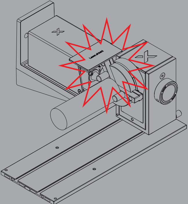
Note: For the 10 W or 20 W laser module, install the laser shield as illustrated. For the 3 W laser module, installation of the laser shield is not necessary.
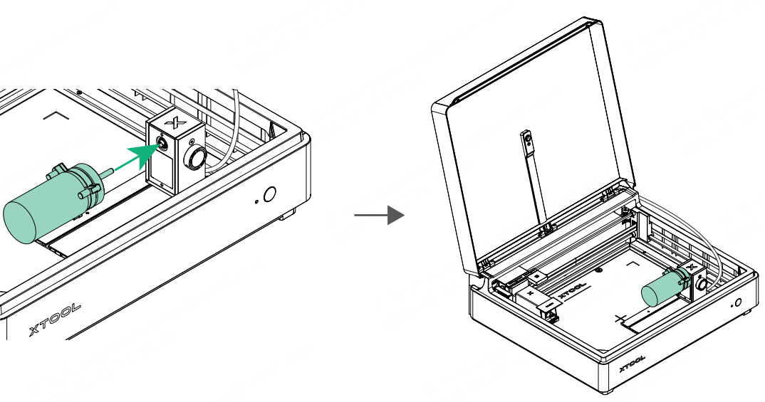
6. Attach the laser module to the horizontal laser emission holder.
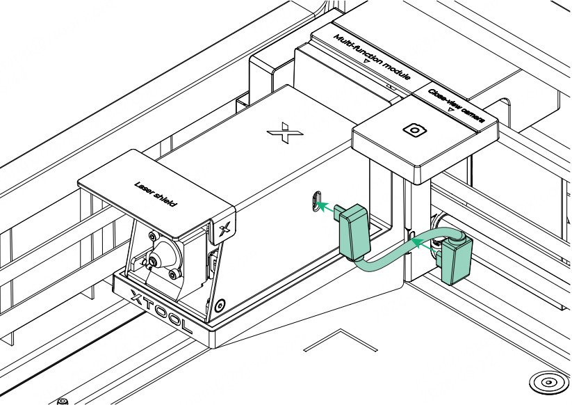
7. Connect the laser module to the device using the module connection cable.
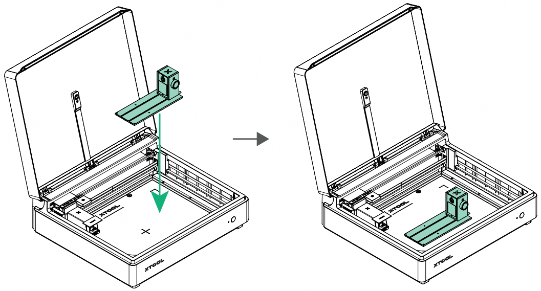
8. Position the assembled power module and main baseplate close to the center of the device.
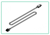
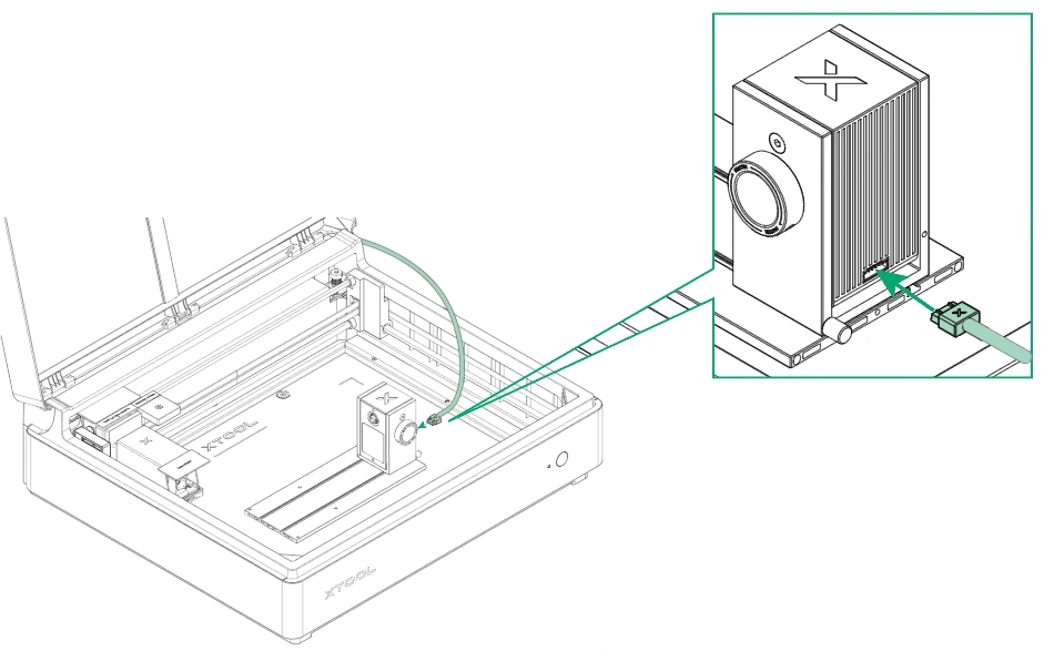
9. Insert one end of the device connection cable into the port on the back of the power module.
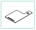
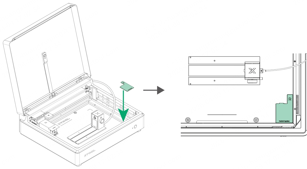
10. Place the positioning plate in the bottom-right corner inside the device.
11. Move xTool Rotary Attachment 3 Lite next to the positioning plate, ensuring it is placed securely against the plate.
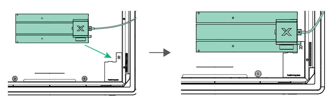
12. Place the other positioning plate on the other side of the main baseplate.
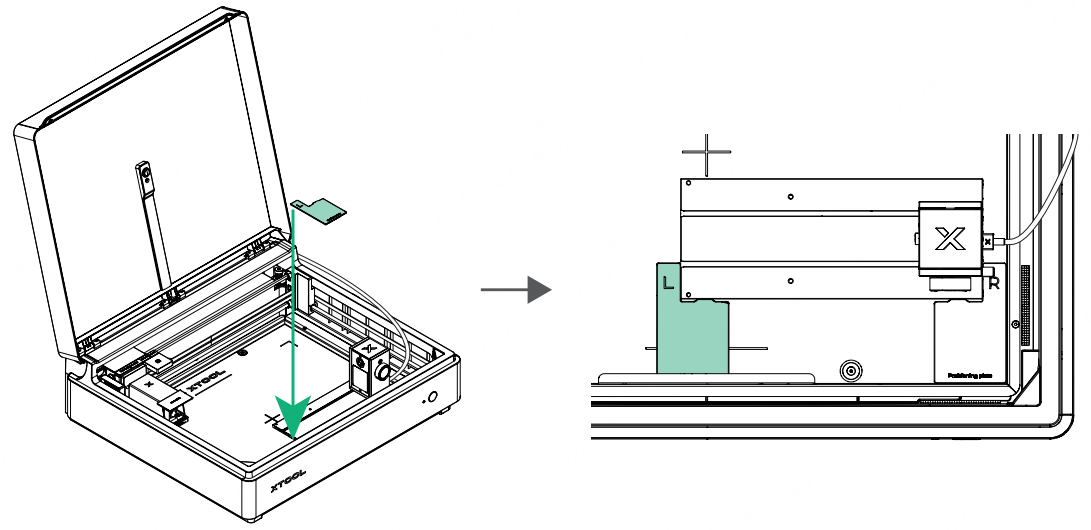
13. Install the workpiece onto xTool Rotary Attachment 3 Lite.
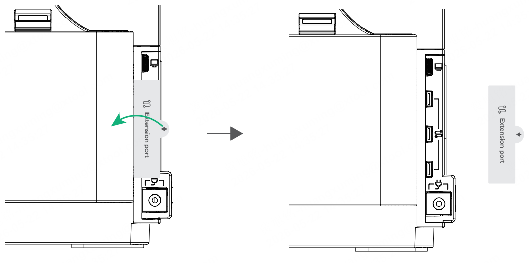
14. Secure the device connection cable to the cable clamps, and insert the other end into any extension port on the device.
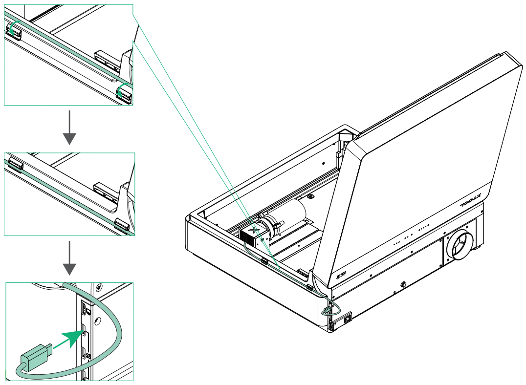
Note: If you have not removed the sticker from xTool M2 extension ports, remove it first, then insert the other end of the device connection cable into any extension port.
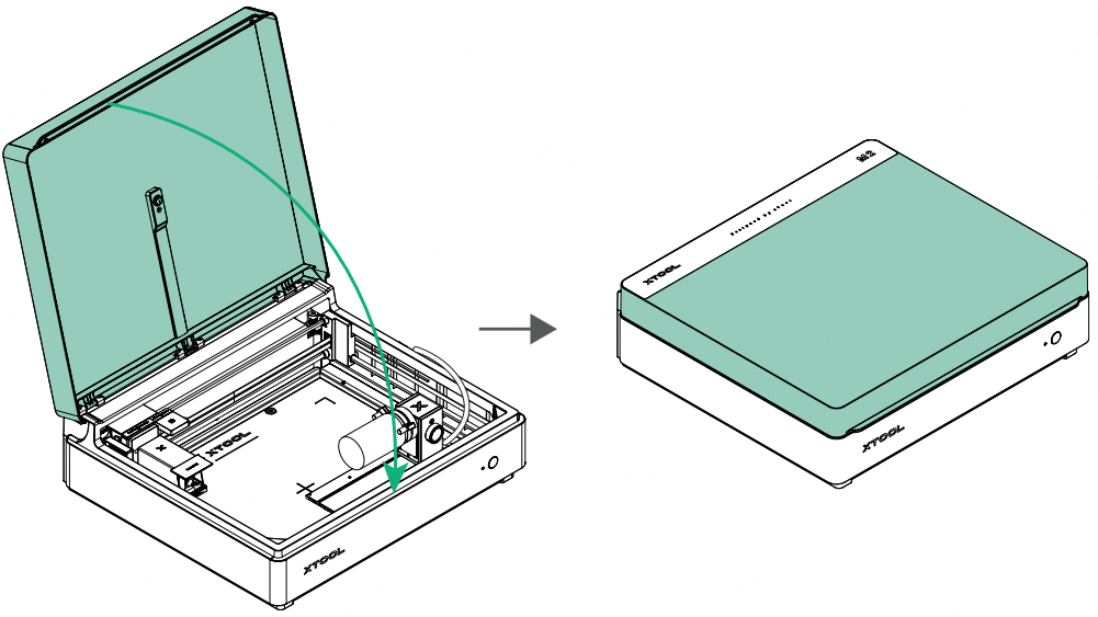
15. Close the lid.
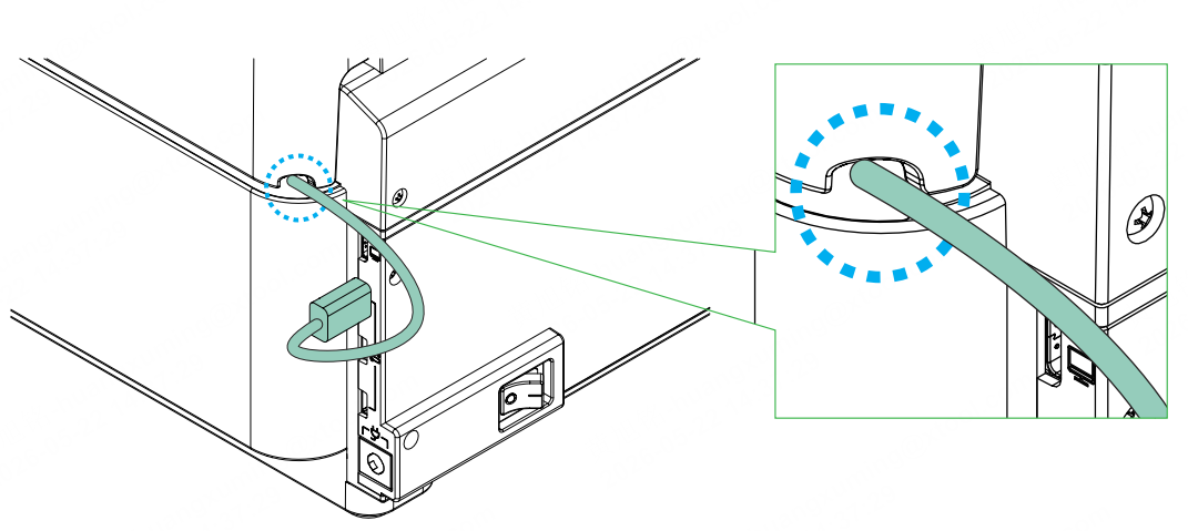
Note: After closing the lid, always check whether the device connection cable is correctly led through the notch in the lid. If it is not positioned properly, open the lid and adjust the cable to ensure it is not squeezed.
16. Download and install the xTool software. Open the software and follow the on-screen instructions to complete the remaining steps. For more details, click here.