Read Before Starting Inner Engraving
Before you begin, please complete the following steps for physical machine setup:
- Switch the Lens: Follow the software instructions to switch to the "Inner-Engraving Lens". You can also watch the video Replace the Field Lens for xTool F2 Ultra UV to learn how to do it.
- Install the Riser: Attach the Riser platform as required.
- Prepare and Measure the Material: Prepare your glass and take precise measurements of its length, width, and height.
Key Consideration: Material Selection
Please be advised that not all transparent glass is suitable for inner engraving. To achieve optimal results, you must use K9 optical crystal glass. For detailed specifications, please visit: A Guide to Glass for Inner Engraving
Tips About Machine Engraving Area:
- Maximum Engraving Area: The F2 Ultra UV laser supports a maximum inner engraving area of 70(X) × 70(Y) × 150(Z) mm.
- Z-axis Limit: The maximum material height must not exceed the Z-axis limit of 150 mm.
- X Y Dimension Note: While the material's length and width (X Y dimensions) can slightly exceed 70 mm, the engraving must be confined to the central 70 × 70 mm area.
Preparations
1. Connect xTool F2 Ultra UV to xTool Studio
Use the USB cable to connect xTool F2 Ultra UV to your computer.
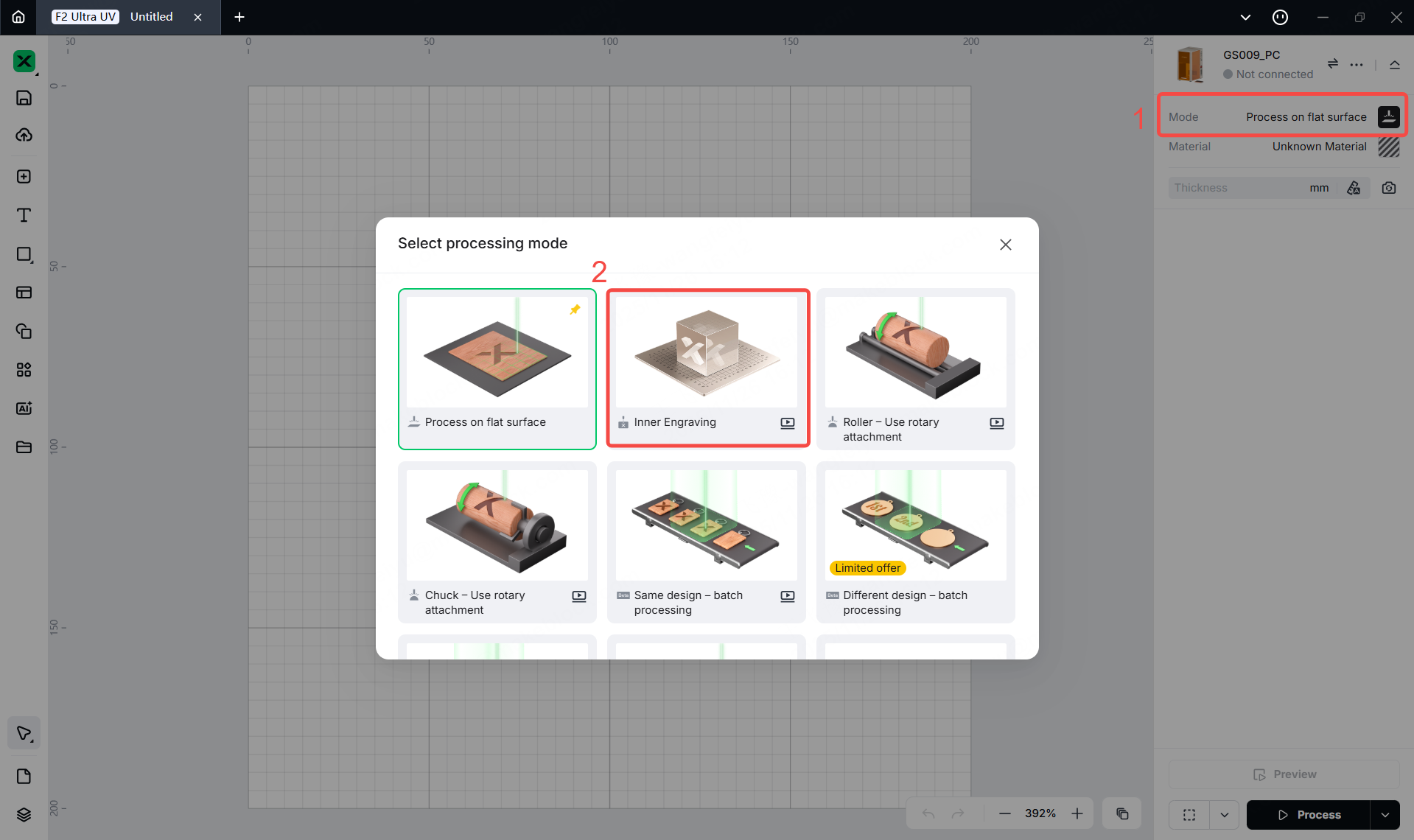
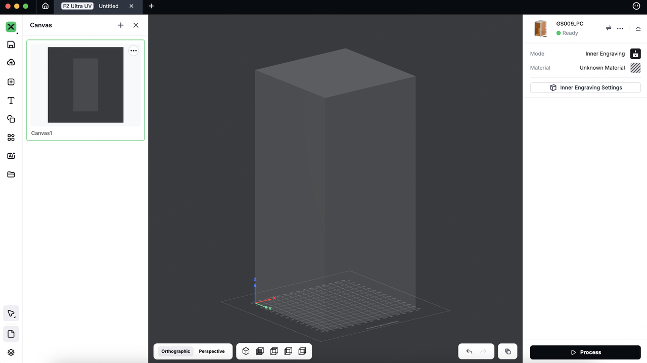
2. Select the processing mode
On the right side of xTool Studio, click the name of mode, and then select inner Engraving as the processing mode.
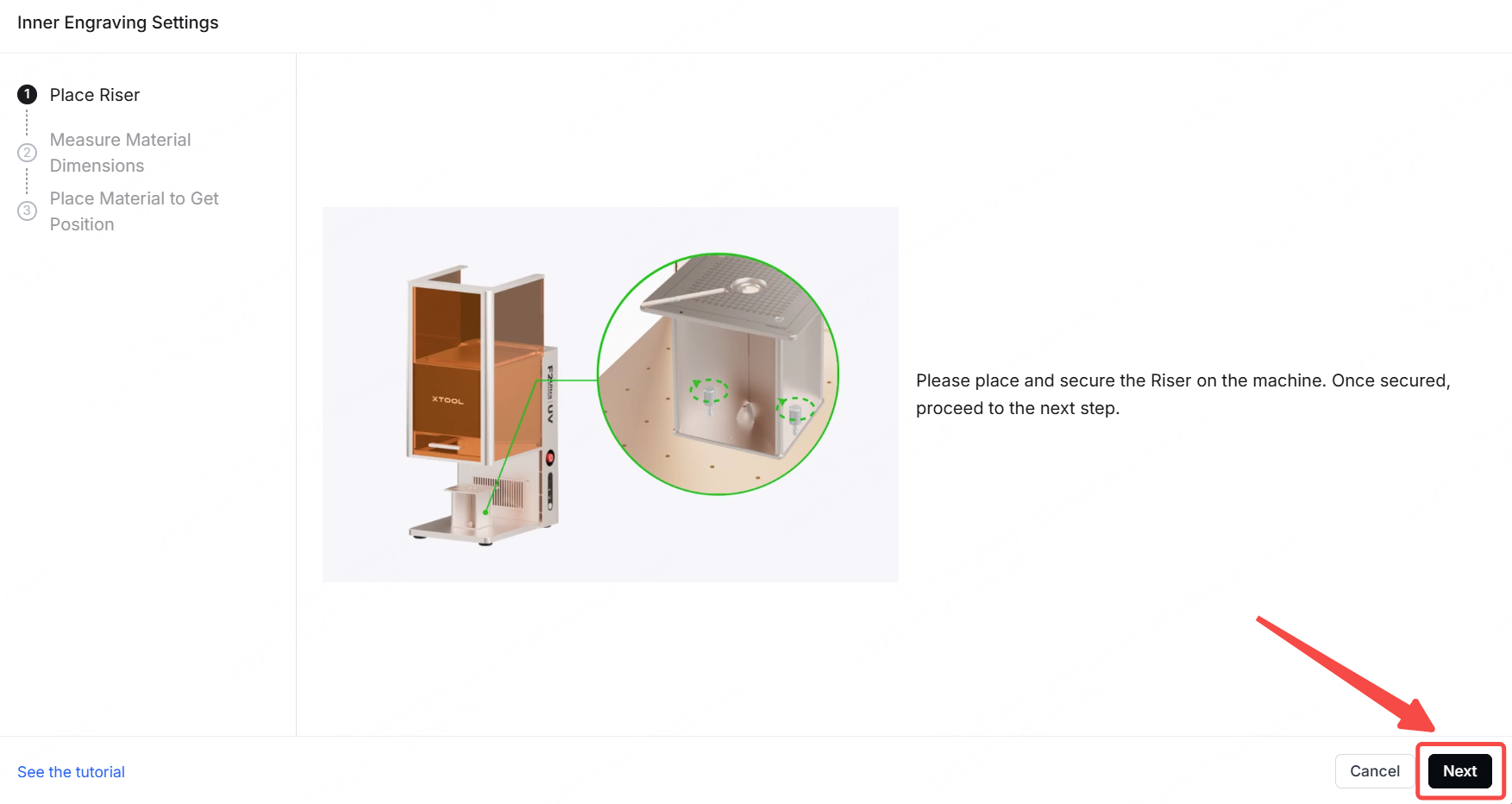
3. Install and Place the Riser
Please place and secure the Riser on the machine. Once secured, click 'Next' to proceed.
4. Select and Measure the Material
Important Notes: Make sure the dimensions you enter match the actual dimensions of the material being processed.For details, please refer to: A Guide to Glass for Inner Engraving
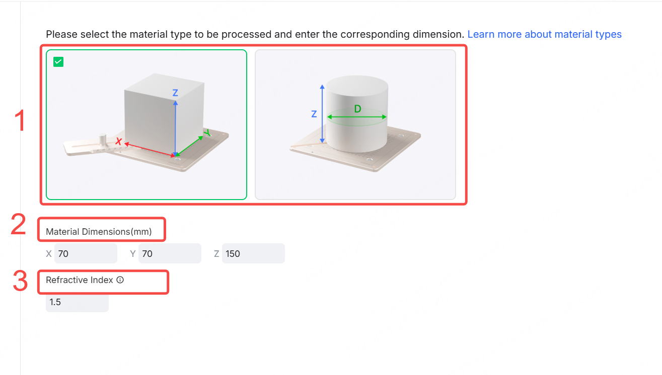
(1) Material Selection & Dimension Entry
Please select the material you wish to process and enter its corresponding dimensions (Length X, Width Y, Height Z or diameter) as guided by the diagram.
(2) Refractive Index Parameter
- When using official K9 glass, the default refractive index is set to 1.5.
- If using other types of glass, you may need to manually calculate this parameter.
5. Position the Material
This step is used to determine the precise position of the glass material on the processing platform.You can define the position by either:
- Using Positioning piece: Enter the numerical values marked on the clips.
- Entering Bottom-Left Corner Coordinates: Directly input the X and Y coordinates where the material is placed.
|
|
Positioning piece | Bottom-Left Corner Coordinates |
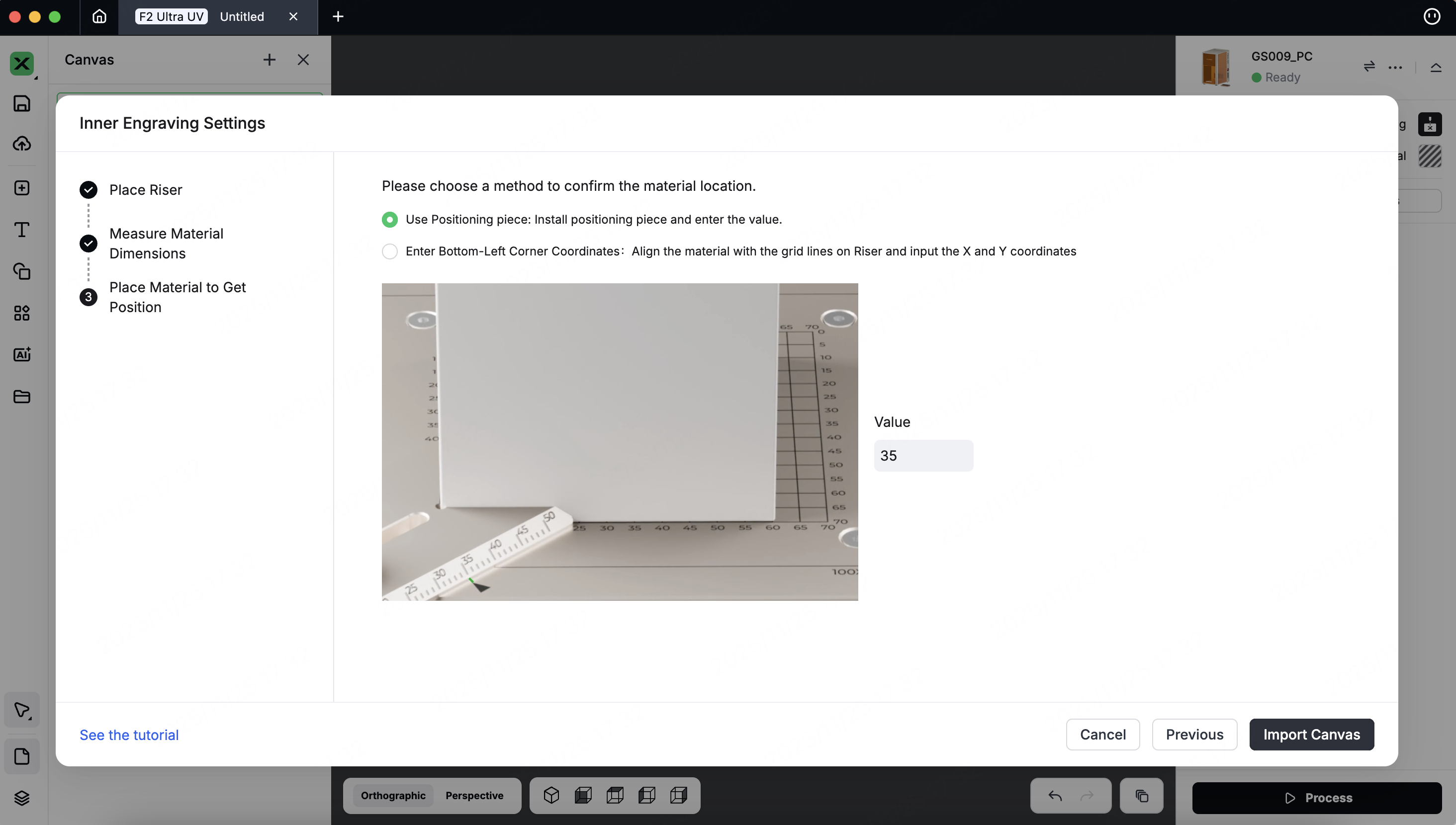
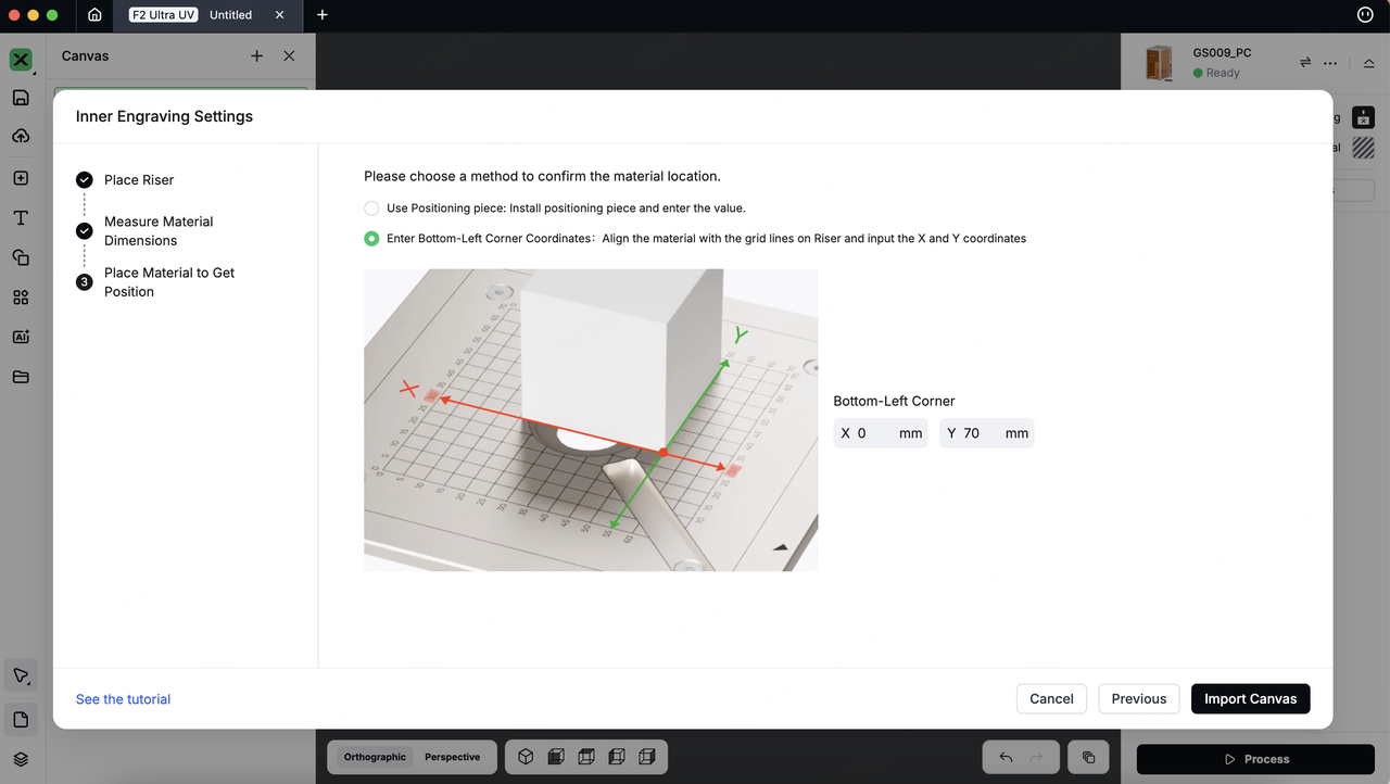
Click 'Import Canvas', Based on the position data you enter, the software will render a frame representing the material and its exact location on the canvas in real-time.
6. Prepare Your 3D Model
(1) Import an Existing Model
When you use F2 Ultra UV and select "Inner Engraving," the software will activate 3D Mode.
You can download a 3D model from the Internet or create one in third-party software, and then import the model to xTool Studio.
Notes:
- Supported 3D Model Formats: STL, OBJ, AMF, 3MF, GLB, PLY
- We recommend the model size not exceed 100MB, as larger files may cause loading delays.
On the left side of the project editing page, click the import icon to import a depth map.You can also drag and drop the files onto the canvas.
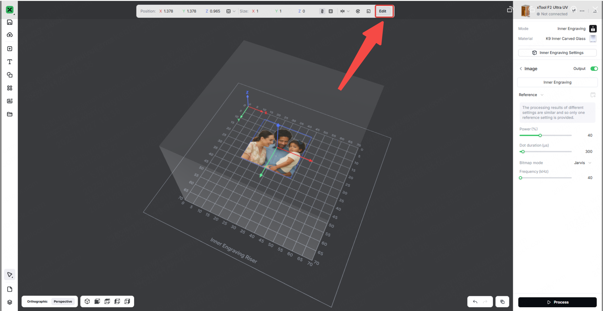
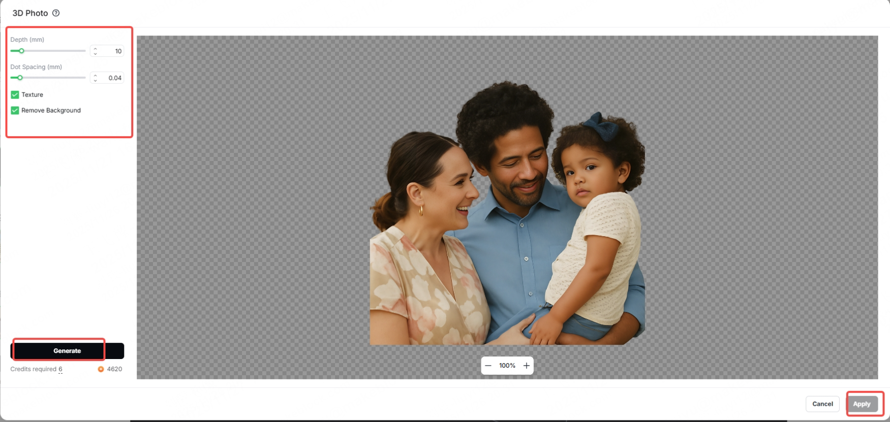
(2) Convert your image into a realistic 3D relief model.
[1] First, import a 2D image into the canvas. Then, click the "Edit" button in the editing bar at the top of the canvas.
[2] Then, select '3D Photos' from the 'Adjustments' menu.
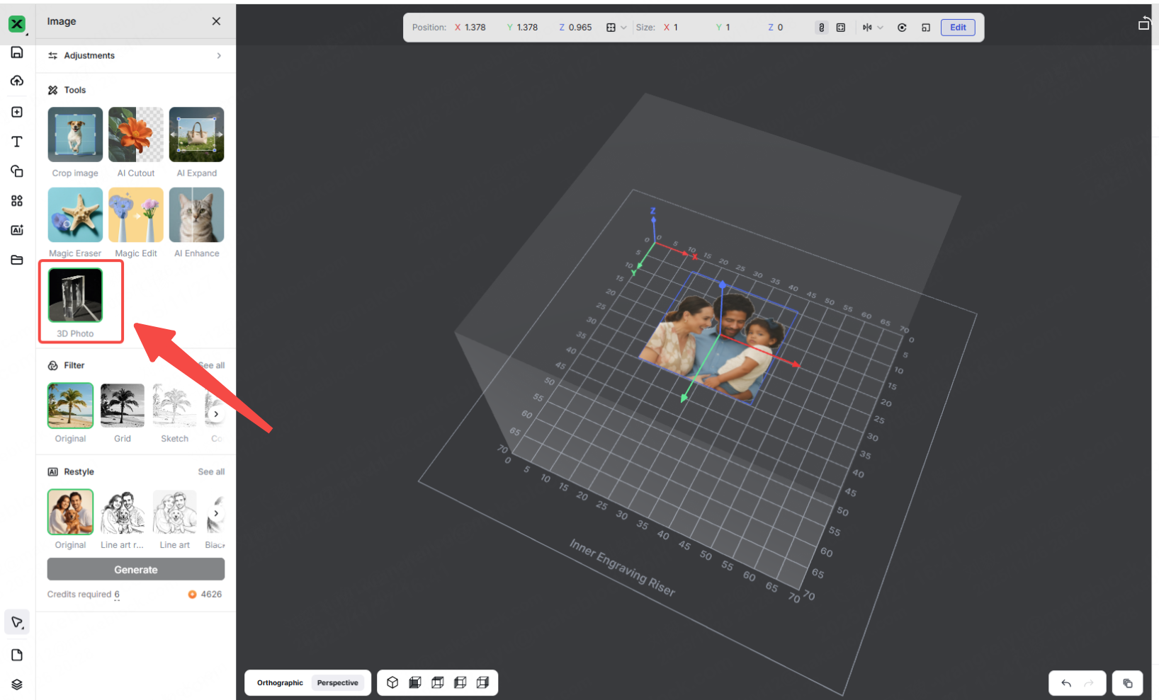
[3] You can then adjust the corresponding elements in the editing panel on the left. Next, click the "Generate" button to create a 3D photo. After reviewing and confirming the photo is satisfactory, click "Apply" to import the 3D photo onto the canvas.
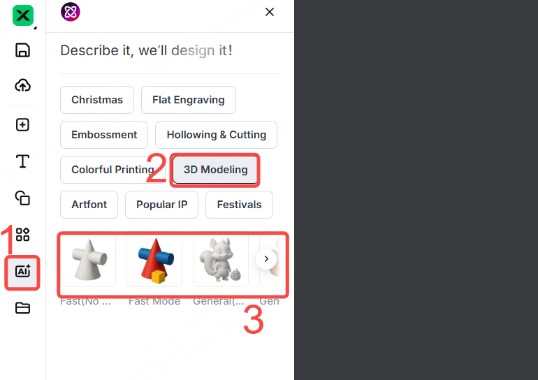
(2) Create a New Model with AImake
[1] On the left side of the project editing page in xTool Studio, click the AI icon. Then, select "3D Modeling" and choose a style you need.
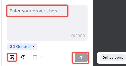
[2] Upload an image or enter a prompt. Finally, click the arrow icon to generate a 3D model.
Start Inner Engraving
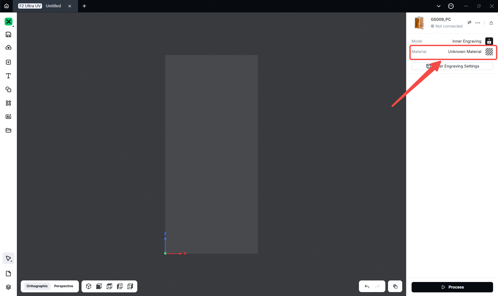
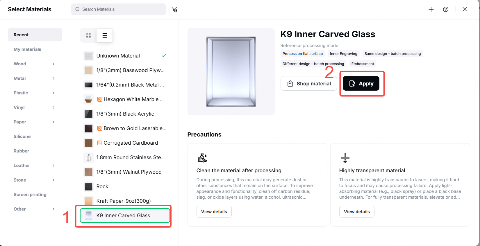
1. Select the Processing Mode and Material Name
(1) In the top-right corner, click Unknown material, select"K9, Inner Carved Glass".Then,the recommended parameters will load automatically.
2. Import a 3D Model
(1)Use the methods described in "Prepare Your 3D Model" to import a 3D model.
(2)Resize the 3D model , and drag the model to move it.
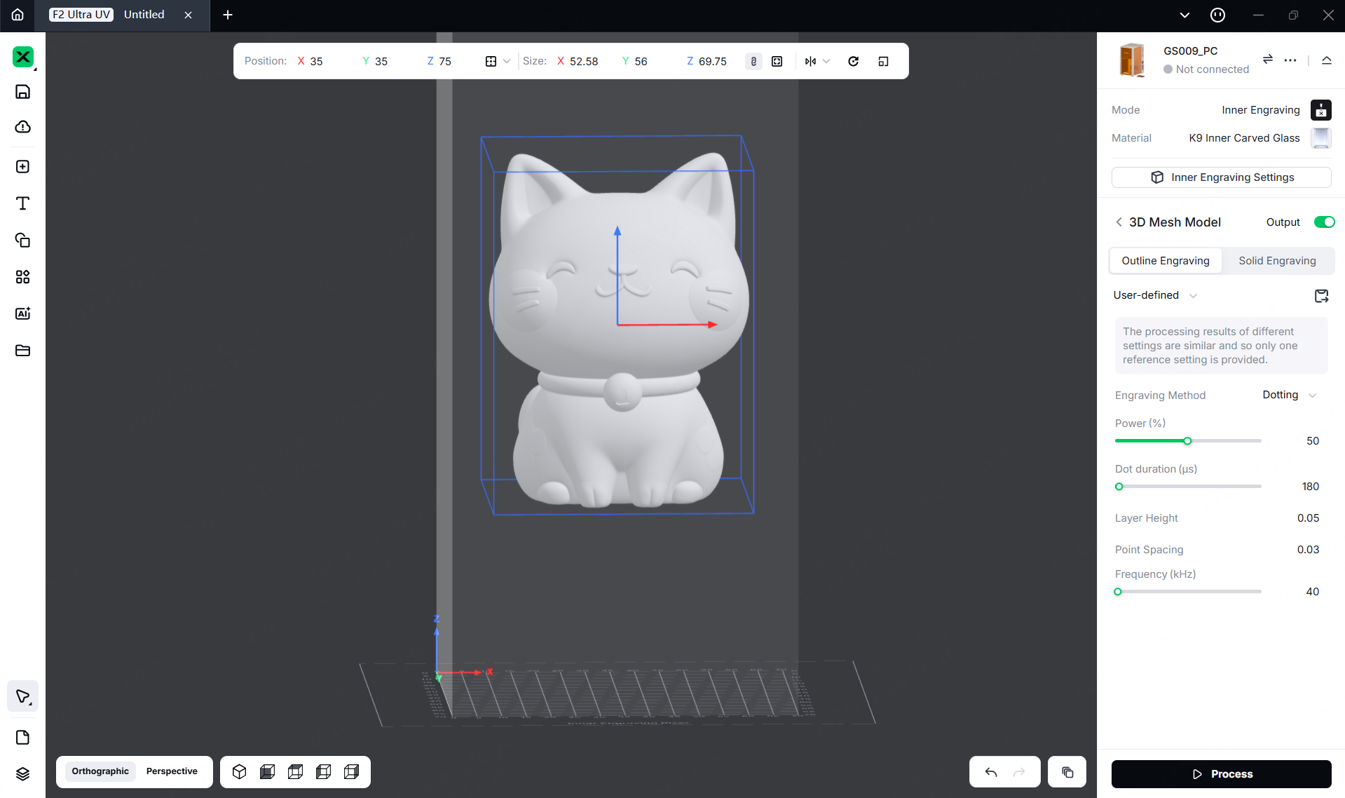
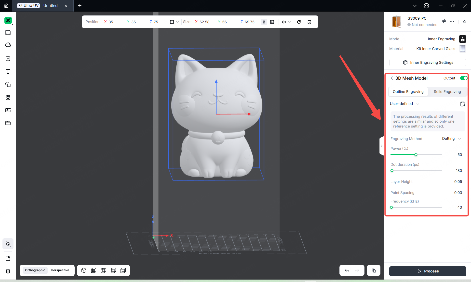
3. Set Processing Parameters
Select the object on the canvas. On the right side of xTool Studio, set parameters for the object.
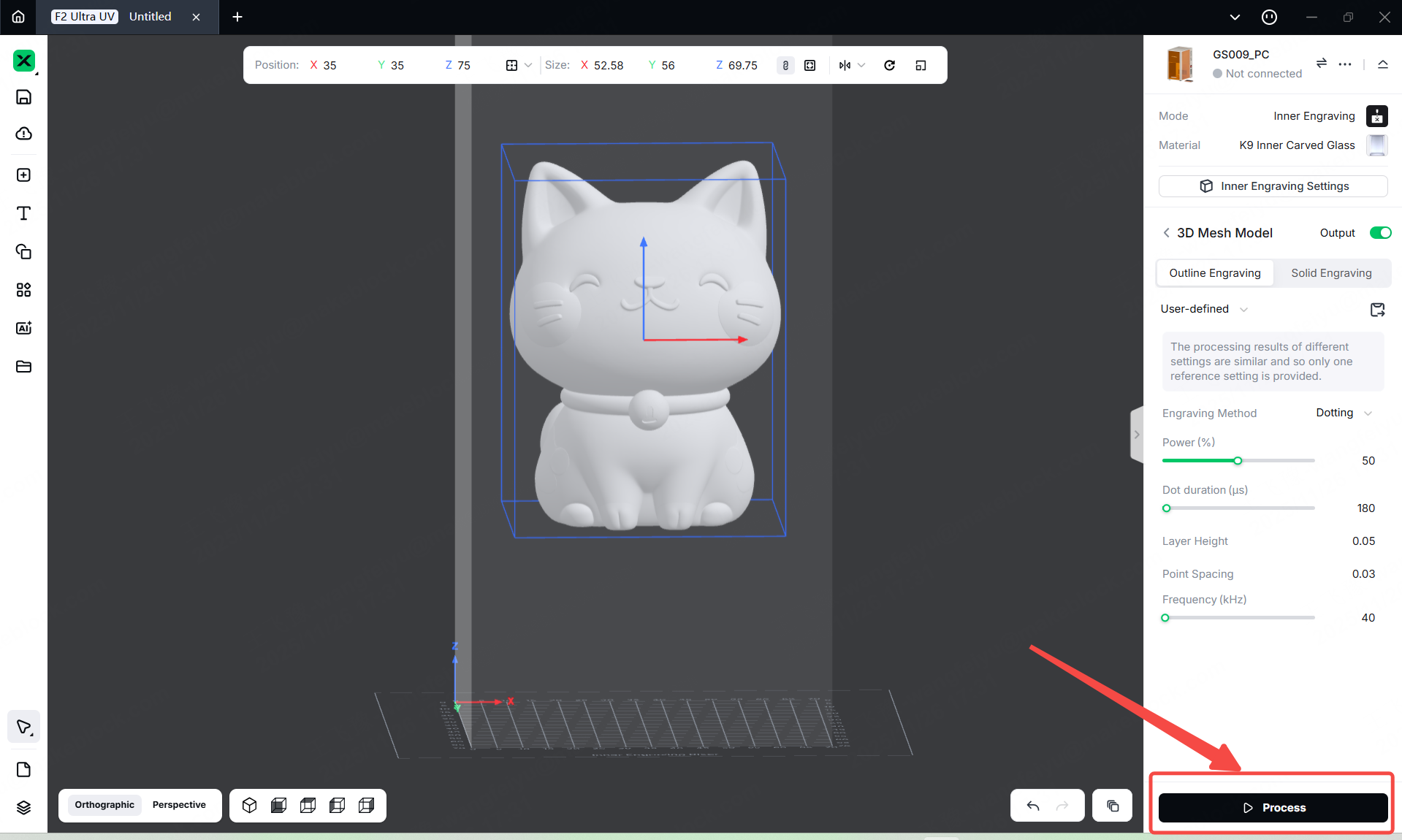
4. Start Processing
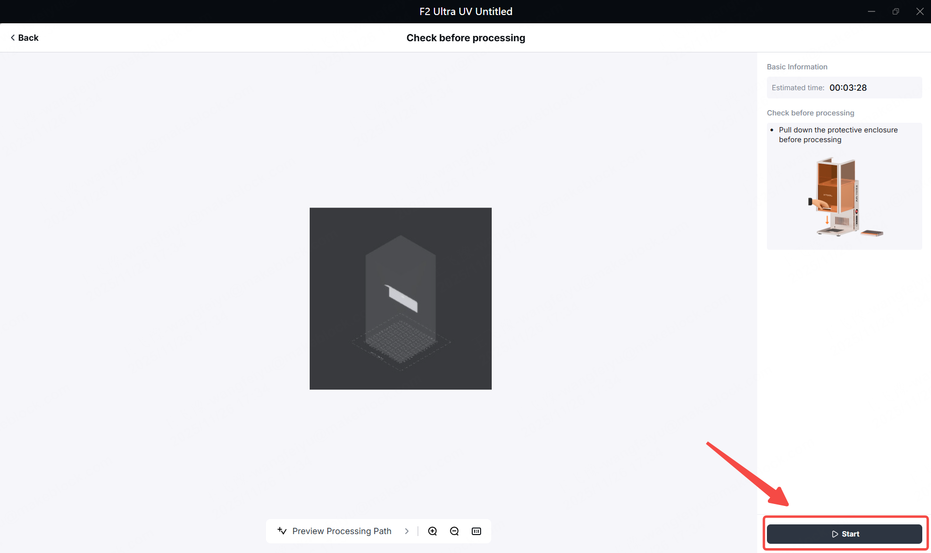
(1) In the bottom-right corner of the software, click 'process'.
(2) Click the "Preview" to Preview the processing design.
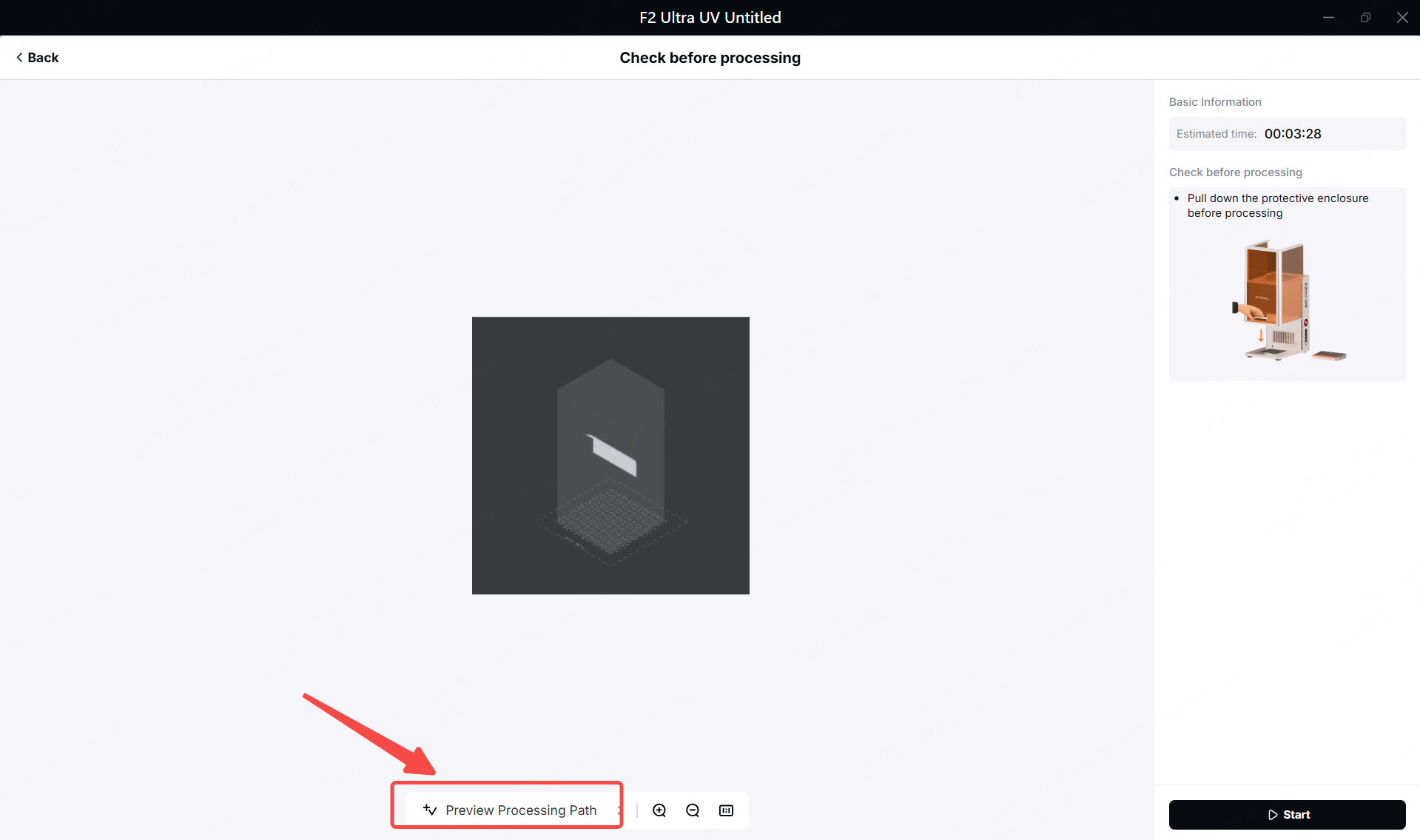
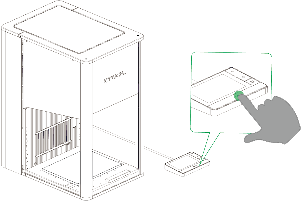
(3) Close the protective enclosure of xTool F2 Ultra UV. In the right corner of xTool Studio, click Start. When the software shows “Ready”, press the XTOOL Start/Stop button on the touchscreen controller to start processing.
FAQ
1. No Engraving Effect
- Surface Contamination
Dust, oil, or other particulates on the glass can block UV laser penetration, as the laser is easily scattered or absorbed by surface impurities. These contaminants may carbonize under laser exposure, further impeding energy transfer and preventing the formation of internal micro-fractures required for engraving.
- Fingerprints or Liquid Residues
Oils or moisture create an optical interface that alters the laser’s refraction path, shifting the focal point away from the intended depth. This misalignment prevents energy concentration inside the glass. Additionally, liquids can generate microbubbles when heated, disturbing energy distribution and compromising engraving results.
- Incorrect Engraving Parameters
Improper settings—such as focal deviation, excessive speed, or inappropriate pulse frequency—can prevent the laser from reaching the energy threshold needed for internal modification. Incorrect focus or speed limits stress induction, while unsuitable pulse rates affect energy accumulation, inhibiting micro-fracture formation.
- Insufficient Laser Power
UV lasers have limited energy density. If the power falls below the critical threshold for internal engraving, the laser cannot overcome molecular bonds in the glass. This results in negligible structural change, producing only faint marks or no visible effect, even with otherwise correct parameters.
2. Blurry or Unclear Engraving Result
- Unadjusted 3D Model Proportions
Directly engraving a 3D model without scaling it to match the glass thickness, effective engraving depth, and laser focal range can cause part of the model to fall outside the engraveable area. This leads to misplaced or distorted details. Additionally, if the model size does not align with the laser's travel range, edges may be compressed or overlapped, resulting in blurred output.
- Excessive Laser Power
Overpowering the UV laser can generate too many micro-explosion points inside the glass. These tend to overlap or spread, blurring boundaries and reducing clarity. Excessive energy may also cause internal stress fractures, creating a cloudy or diffuse appearance, and in severe cases, complete loss of fine details.
- Improper Point Spacing & Layer Height
Oversized point spacing creates gaps and a grainy, incomplete engraving. Undersized spacing causes energy overlap, fusing adjacent details. Incorrect layer height—too high causing visible banding, too low causing over-saturation—disrupts depth gradation and structural accuracy, leading to blurred contours and poor model fidelity.
3. Internal Cracks Inside the Material
- Excessive Laser Power
When UV laser power exceeds the appropriate threshold for glass inner engraving, the concentrated energy induces intense micro-explosions inside the material. This not only generates the intended micro-fractures but also causes irregular and extended cracking. These cracks can spread and interconnect, compromising contour integrity and, in severe cases, leading to widespread internal fragmentation—rendering the engraving unusable.
- Overly Slow Engraving Speed
An excessively slow speed prolongs laser exposure, causing energy to accumulate beyond the material's tolerance. This amplifies micro-explosion effects, enlarging micro-fractures and promoting uncontrolled crack propagation. The resulting cracks tend to be coarse and uneven, degrading detail definition and overall visual quality.
More information
xTool F2 Ultra UV Unboxing and First Use
Inner Engraving Work Area Calibration
Z-axis Calibration for Inner Engraving
Replace the Field Lens for xTool F2 Ultra UV
A Guide to Glass for Inner Engraving
Inner Engraving Operation Guide for Glass Materials
Approaches to Improving Inner Engraving Results
Inner Engraving File Types for xTool F2 Ultra UV
Failure to Perform Inner Engraving on Glass
Crystal Ball Inner Engraving Operation Instructions
Crystal Ball Inner Engraving Operation Instructions (Without the K9 Crystal Ball Inner Engraved Kit)
