Download PDF files (multi-language)
xTool F2 Ultra UV Quick Start Guide
Inner Engraving Pack User Manual
xTool F2 Ultra UV unboxing and first use
To ensure proper use, refer to the safety instructions for xTool F2 Ultra UV.
Models by laser safety class
Lasers are categorized into several different classes depending on the extent of the potential hazard associated with the laser, with Class 1 being the least dangerous and Class 4 the most dangerous.
The differences between Class 1 and Class 4 models of xTool F2 Ultra UV are as follows:
Model | Item | Product structure | Assembly | Safety information |
|---|---|---|---|---|
Class 1 laser model (Model: MXF-K007-001) | Key and inner engraving pack not included | Without the emergency stop button | Key insertion and emergency stop button check not required | During operation, the protective enclosure remains closed to prevent human access to laser radiation beyond Class 1. |
Class 4 laser model (Model: MXF-K007-002) | Key and inner engraving pack included | With the emergency stop button | Key insertion and emergency stop button check required | During operation, if the protective enclosure is open, you may be exposed to Class 4 laser radiation. The Class 4 laser machine is intended for use by trained professionals only. |
List of items
Item name | Image |
|---|---|
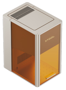
xTool F2 Ultra UV |
|
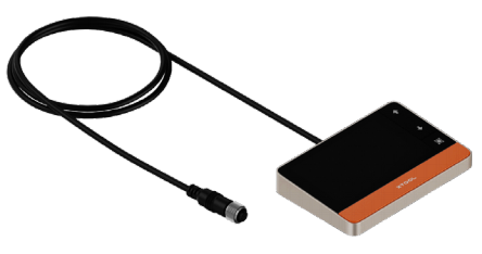
Touchscreen controller |
|
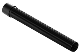
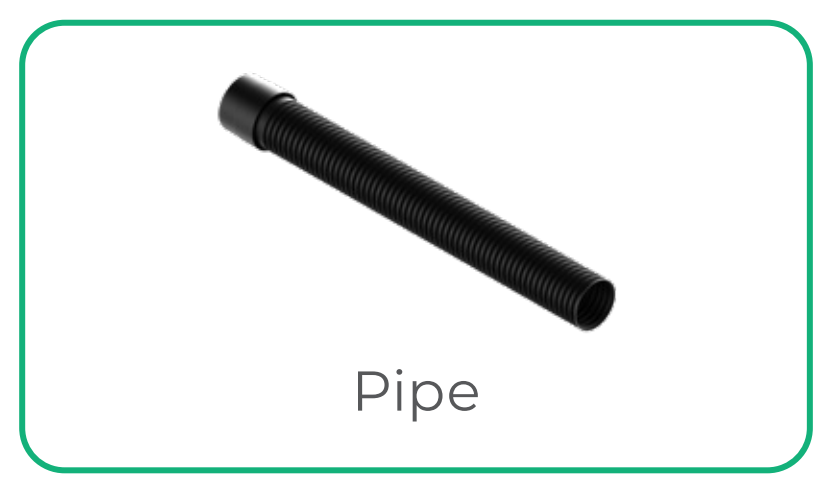
Pipe |
|
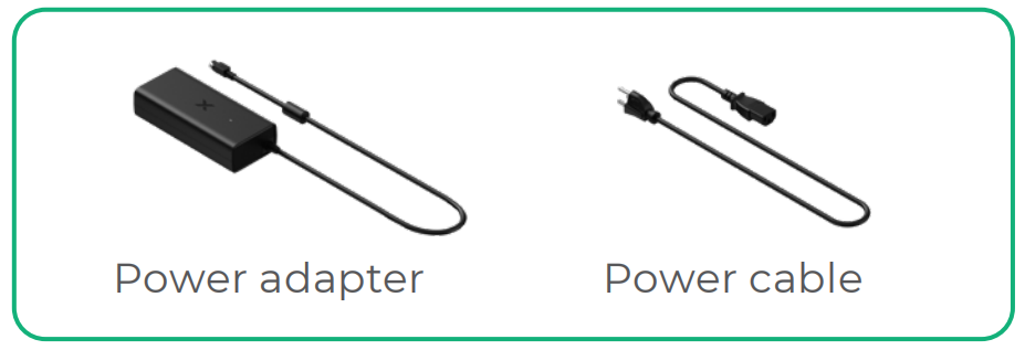
Power adapter |
|
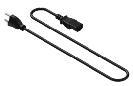
Power cable |
|
USB cable |
|
Key |
|
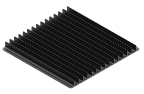
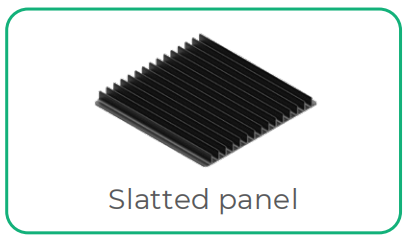
Slatted panel |
|
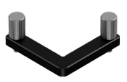
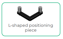
L-shaped positioning piece |
|
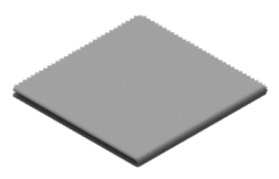
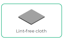
Lint-free cloth |
|
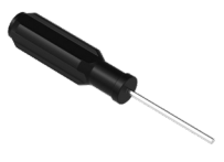
Screwdriver 2.5 mm |
|
Surface engraving material pack |
|
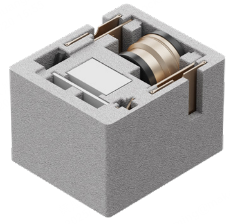
Inner engraving pack |
|
Quick start guide |
|
Safety instructions |
|


The key and inner engraving pack are not included with Class 1 laser machines.
The power cable may vary according to kits. The illustration is for reference only.
Meet xTool F2 Ultra UV
Product structure
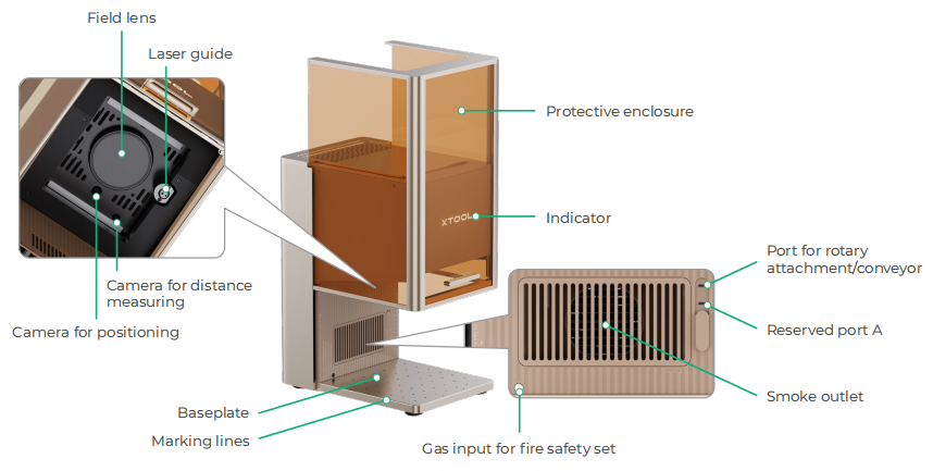
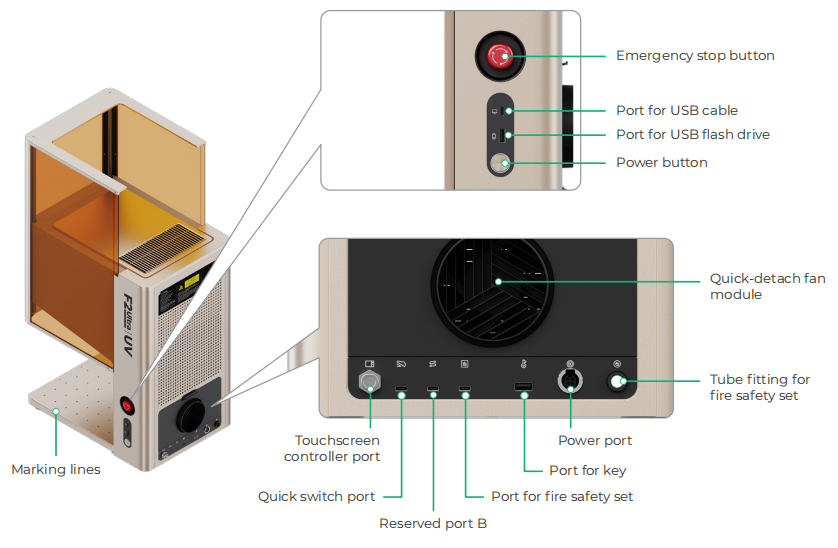
Reserved port A and reserved port B function differently and can not be used interchangeably.
Class 1 laser machines do not include an emergency stop button.
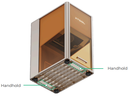
By gripping on the handholds, you can easily move the machine.
Touchscreen controller
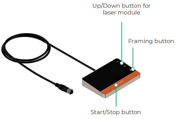
■ Up/Down button for laser module: Lifts or lowers the laser module during manual focusing.
■ Framing button: Press it once to start or stop framing.
■ Start/Stop button: Press it once to start or stop material processing; press it twice consecutively to repeat the last processing task.
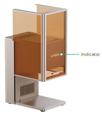
Common machine states and indicator display
Indicator display | Machine state | |
|---|---|---|
Solid on | Powered on | |
Blinking slowly | Processing | |
Blinking rapidly | Setting network / Upgrading firmware | |
Going off | Sleeping / Powered off | |
Specifications
Product name | xTool F2 Ultra UV |
|---|---|
Working laser | 5 W UV laser |
Working laser wavelength | 355 ± 5 nm |
Surface engraving work area | 200 mm × 200 mm |
Inner engraving work area | 70 mm × 70 mm |
Maximum processing speed | 15,000 mm/s |
Connection mode | Wi-Fi, USB, IP |
Size (W × D × H) | 294 mm × 429 mm × 520 mm |
Voltage | 110 V / 220 V |
Install xTool F2 Ultra UV
1. Detach the field lens protector.
Ensure that the protector is removed every time before you use the machine. If you won't use the machine for a long period of time, you can install the protector back to prevent the field lens from getting dusty.
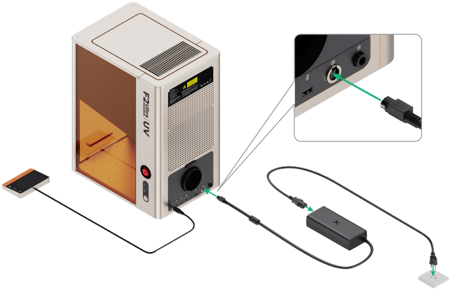
2. Connect the touchscreen controller.
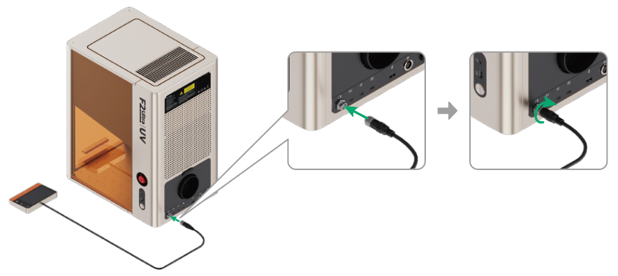
Ensure that the side with the notch faces upward.
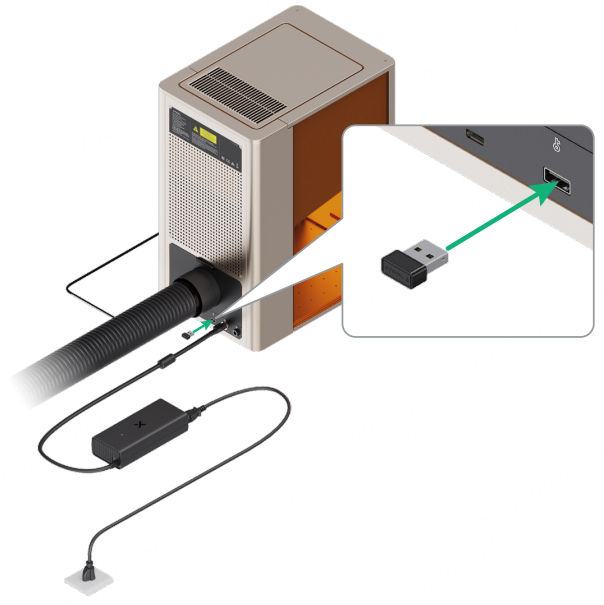
3. Connect to a power supply.
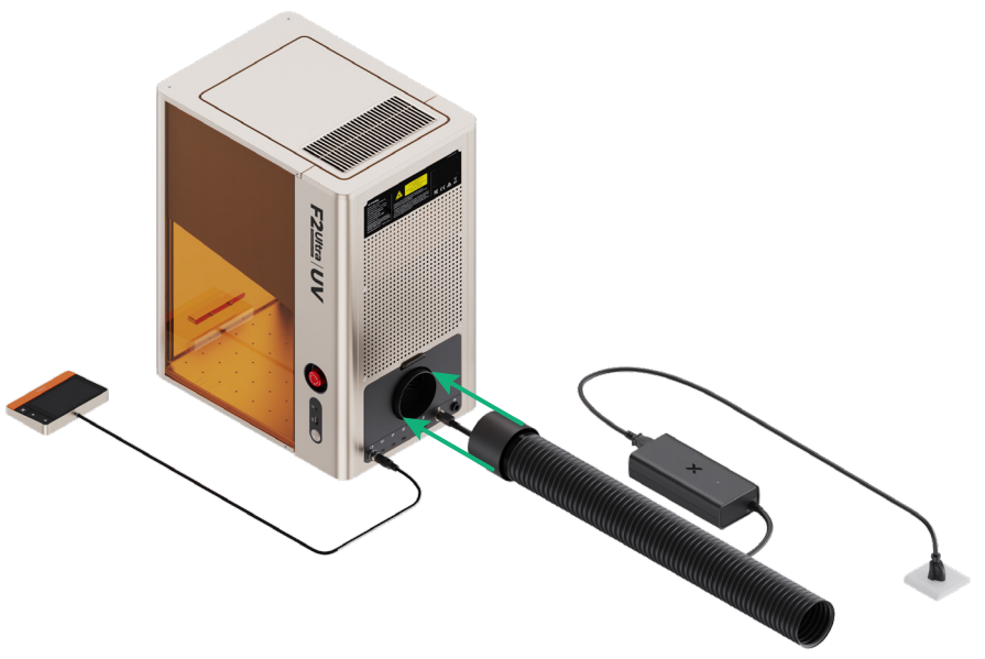
4. Install the pipe.
Steps 5 and 6 do not apply to Class 1 laser machines.
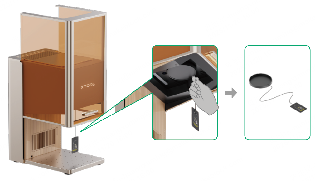
5. Insert the key.
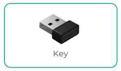
You can use the key either as an access-control key or a remote interlock connector.
Access-control key
Removing the key can disable the machine's processing and related functions.
Remote interlock connector
For detailed instructions, click here.
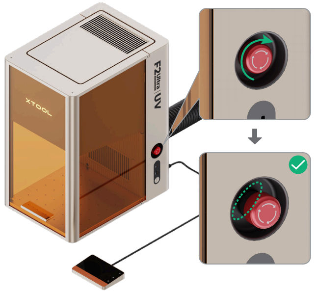
6. Check the emergency stop button.
Ensure that the emergency stop button is released. If it is pressed, rotate to release it.
Emergency stop button
If an emergency occurs, press the emergency stop button to shut off the machine.
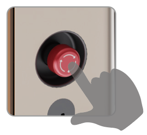
After dealing with the emergency, rotate the emergency stop button to release it.
Use xTool F2 Ultra UV
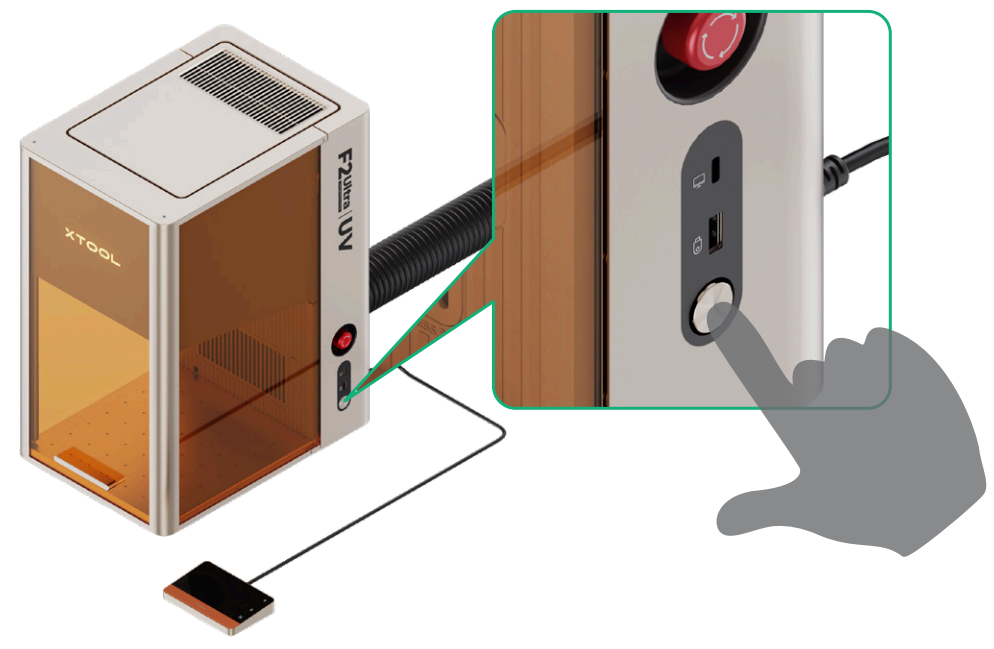
Power on
Press the power button to turn on xTool F2 Ultra UV.
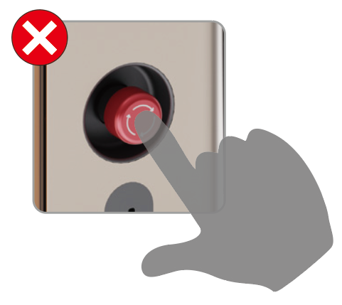
For Class 4 laser machines, never use the emergency stop button as a power button.
Use the emergency stop button only when an emergency occurs. Using it as a power button to turn the machine on or off may cause damage.
To extend the machine’s lifespan, run it at least once a month.
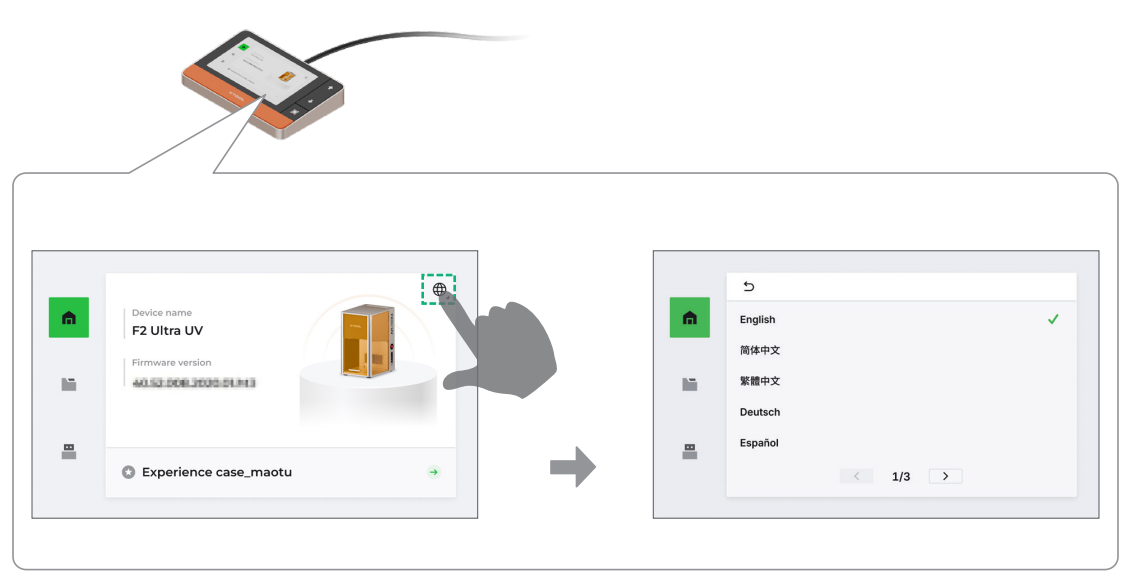
Set the language
Set the UI language on the touchscreen controller.
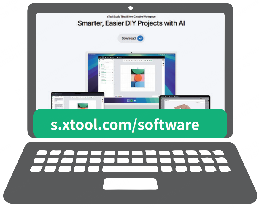
Operate xTool F2 Ultra UV with the software
(1) Visit s.xtool.com/software to download and install the software developed by xTool.
(2) Use the USB cable to connect xTool F2 Ultra UV to your computer, and then connect xTool F2 Ultra UV in the software.
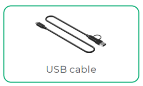
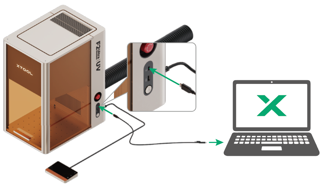
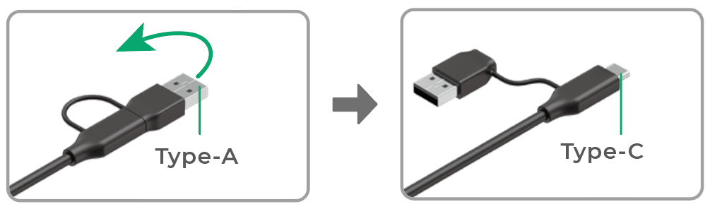
The other end of the USB cable can be connected to a USB Type-A or Type-C port. Choose between the connectors based on your needs.
For details about how to use the software to operate xTool F2 Ultra UV to process materials, click here and go to the "Operation & Features" section.
Use accessories
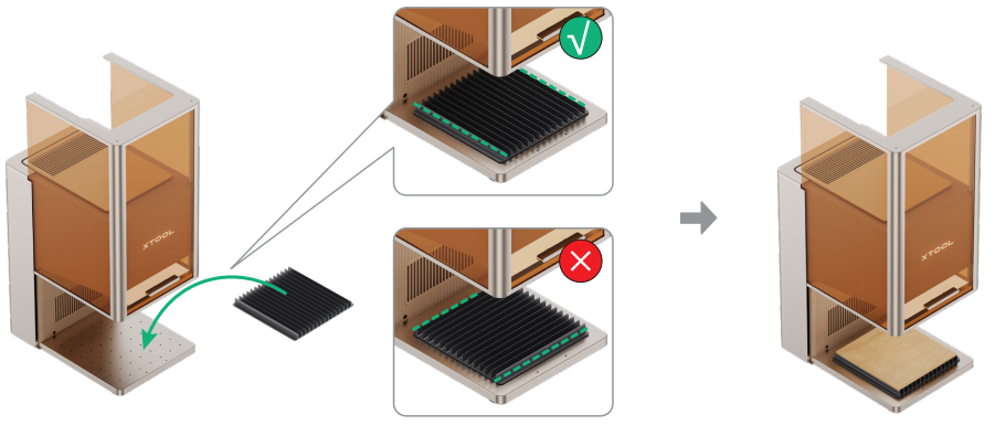
Slatted panel
To cut a material, you are advised to use the slatted panel. It helps reduce burn marks and protects the baseplate during material processing.
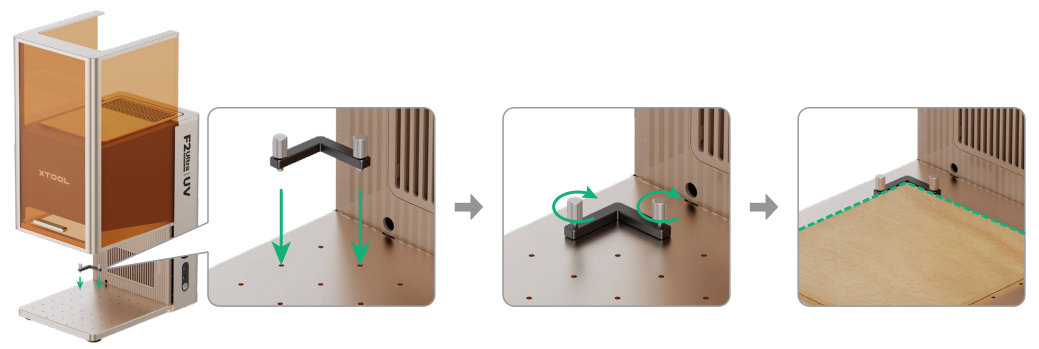
L-shaped positioning piece
You can use the L-shaped positioning piece for batch processing. It helps you place materials in the same position for each processing task.
Maintenance
Disconnect power before maintaining the product.
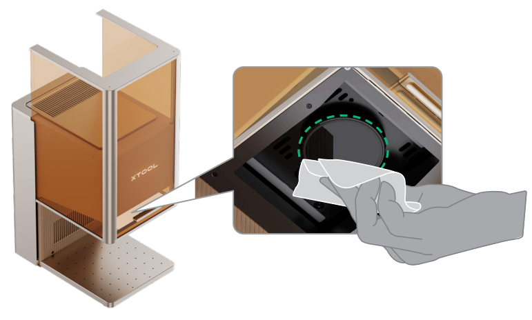
Clean the field lens
When laser power attenuation occurs, for example, engraved patterns are shallow or materials can't be cut as expected, the field lens may get dirty. Clean it with the lint-free cloth moistened with absolute ethanol.
Clean the galvanometer mirrors
After removing the field lens from the device, never touch the two galvanometer mirrors located above it with your hands. Use a lint-free cloth moistened with absolute ethanol to gently clean them only if they appear dirty.
Clean the fan module
When smoke runs out of the protective enclosure, the fan module may be blocked by dust. Clean it to ensure proper smoke exhausting.
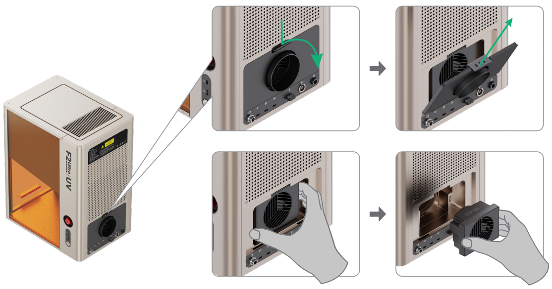
(1) Remove the magnetic fan guard from the smoke outlet.
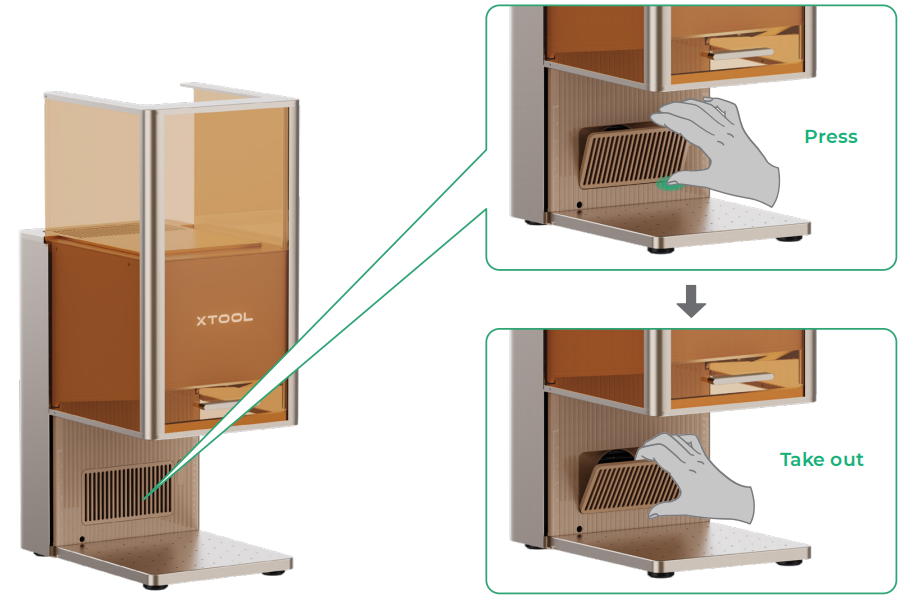
(2) Open the cover, and then take out the fan module.
(3) Open the cover to access the fan.
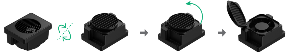
(4) Use a brush or other tools to clean the fan module and the magnetic fan guard. Then, install them back to the main unit.
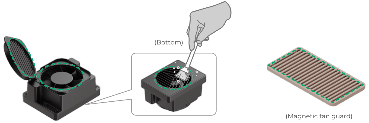
Do not rinse or immerse the fan module in water, as it may damage the circuit.
It is recommended that you perform the following two key steps at least once a month.
1. Turn on and dry the device for 30 minutes.
Turn on your F2 Ultra UV and keep it running for at least half an hour. This operation allows the device to generate heat while running, automatically drying internal moisture and effectively protecting the UV laser core components that are sensitive to humidity.
2. Check the surfaces of the field lens and the galvanometer mirrors.
Ensure that the surfaces of the field lens and the galvanometer mirrors are clean and free of debris. Dust or dirt on these components can significantly reduce processing quality and may cause degradation or damage.
Why are the above two operations important?
- Prevent irreversible damage: Your F2 Ultra UV is equipped with a precise ultraviolet laser. If the device remains unused for an extended period—for example, over six months—especially in humid environments, the aging of its critical components, such as the frequency-doubling crystal, could accelerate, potentially leading to irreversible performance degradation.
- Maintain consistent results: Keeping the field lens and galvanometer mirrors clean is fundamental to achieving optimal processing results.
Other maintenance tips:
- Use the device in a temperature-controlled environment (10–30°C or 50–86°F).
- Use the device in a dry and well-ventilated area. Avoid using it in humid environments.
- If the device will not be used for an extended period, store it in a dry environment.
Dos and don'ts
Surface engraving lens and inner engraving lens replacement
Disconnect power before lens replacement.
Follow the guidelines below for lens replacement.
1. NEVER touch the galvanometer mirrors with your hands! After removing the field lens, under no circumstances should you touch the two galvanometer mirrors inside the device with your hands.
2. The field lens and galvanometer mirrors must be kept absolutely clean.
3. To clean the field lens (surface engraving lens or inner engraving lens), use a lint-free cloth moistened with absolute ethanol.
4. To clean the galvanometer mirrors, use a lint-free cloth moistened with absolute ethanol to gently wipe them only if you confirm the presence of dirt or contamination.
[IMPORTANT] Failure to maintain the cleanliness of the optical components in a timely manner can result in minor issues such as power attenuation, reduced beam quality, and poor processing results, or in severe cases, permanent damage to the optical components!
Slatted panel
The slatted panel serves to provide support, guide airflow, and protect the device’s baseplate during use. When engraving thin or transparent materials, use the slatted panel to avoid damaging the device’s baseplate.
Riser for inner engraving
The riser for inner engraving serves as a support and positioning tool during use. During the inner engraving process of a glass workpiece, if the engraved model is low and the focal point is close to the riser top plate, there is a risk of damage to the riser top plate. Please use it with caution.
Emergency stop button
The emergency stop button is used to cut off the device's power supply in emergency situations. Do not use the emergency stop button as the device's power button.
