Note: |
|---|
Why you need it
To prevent issues, it's recommended to first test and calibrate the optical path when encountering the following scenarios:
- Before starting the initial processing task: After you unbox and set up xTool P2 as instructed in the quick start guide, please test the optical path before use to ensure proper material processing.
- After cleaning/replacing mirrors.
- When no laser is coming out from the laser module.
- When there is a noticeable decrease in processing power.
Tools you need
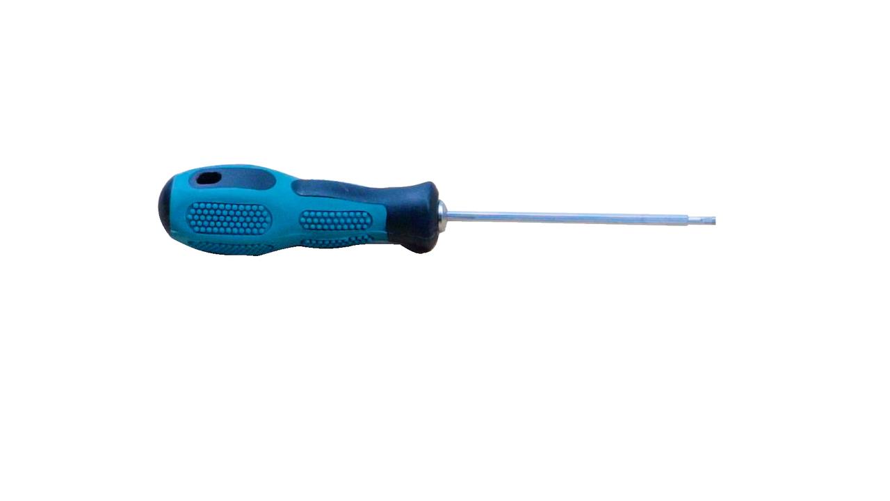
The two-in-one screwdriver that comes with the pack |
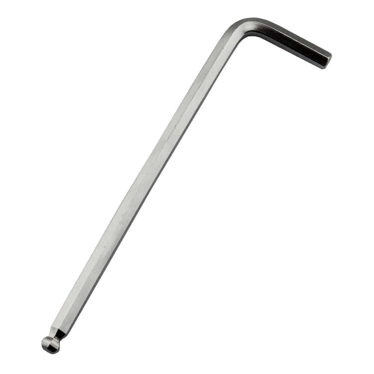
The 1.5 mm hex key that comes with the pack |
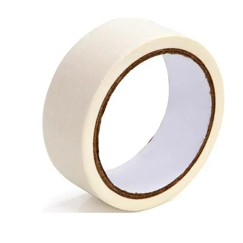
Masking tape (During the calibration process, multiple pieces from a single roll should be prepared in advance.) |
Things to know beforehand
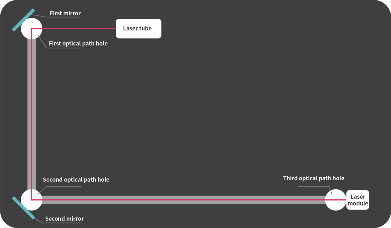
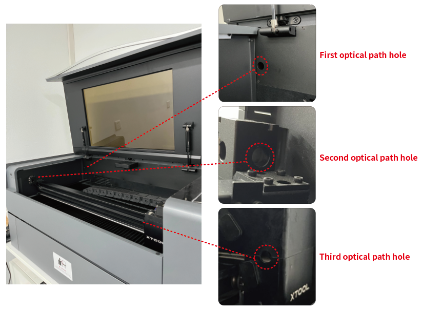
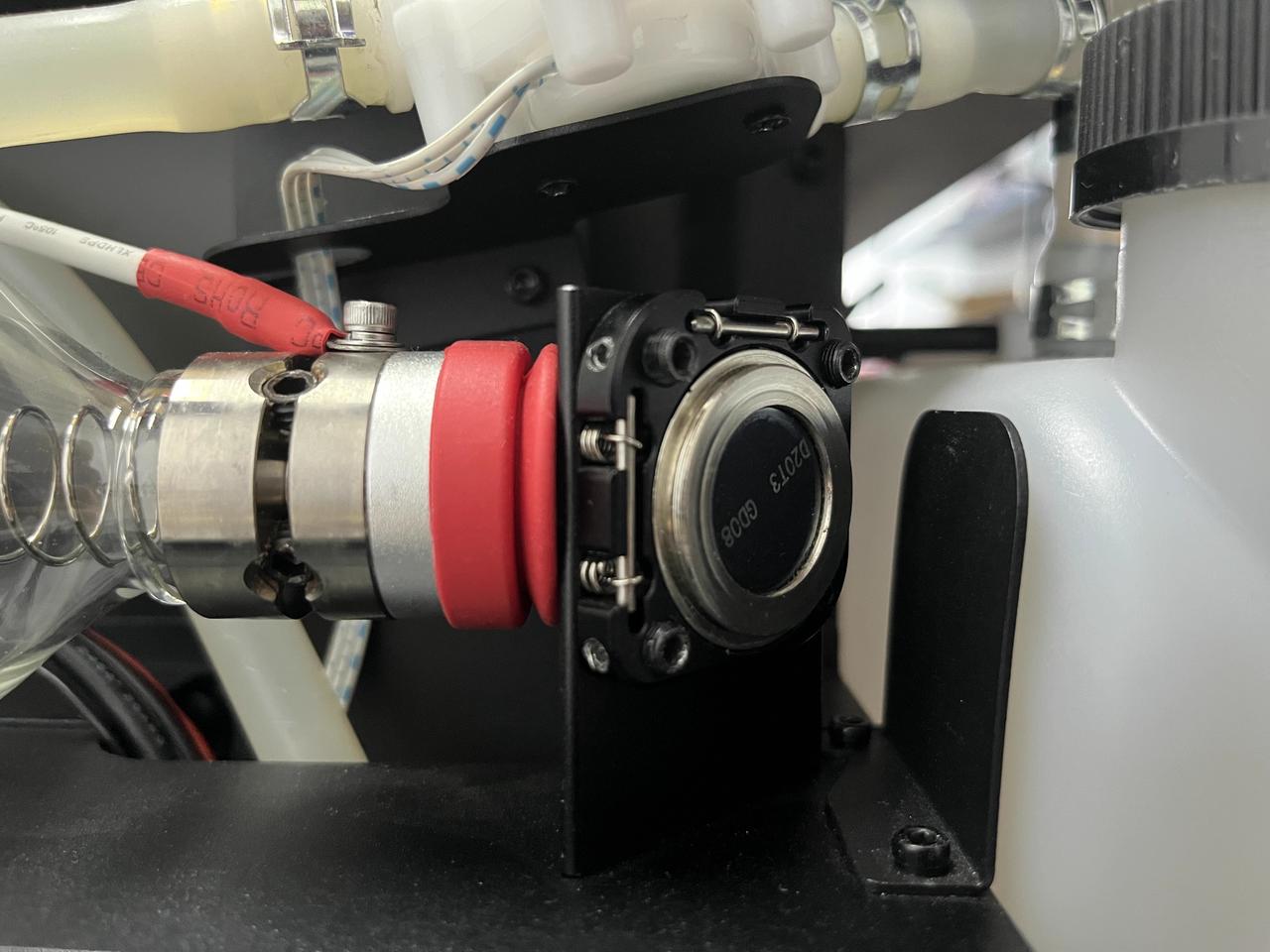
Understand the optical path structure of xTool P2
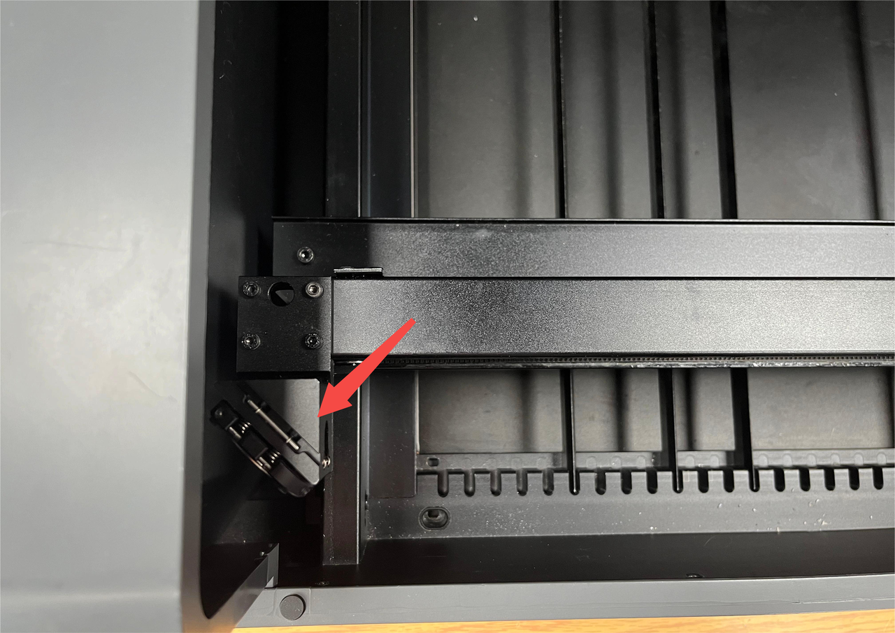
A laser beam is produced by the laser tube, reaches the first mirror, passes through the first optical path hole, reaches the second mirror, passes the second optical path hole, and then reaches the laser module through the third optical path hole, as shown in the following figure.
How to confirm the deviation
Note: |
|---|
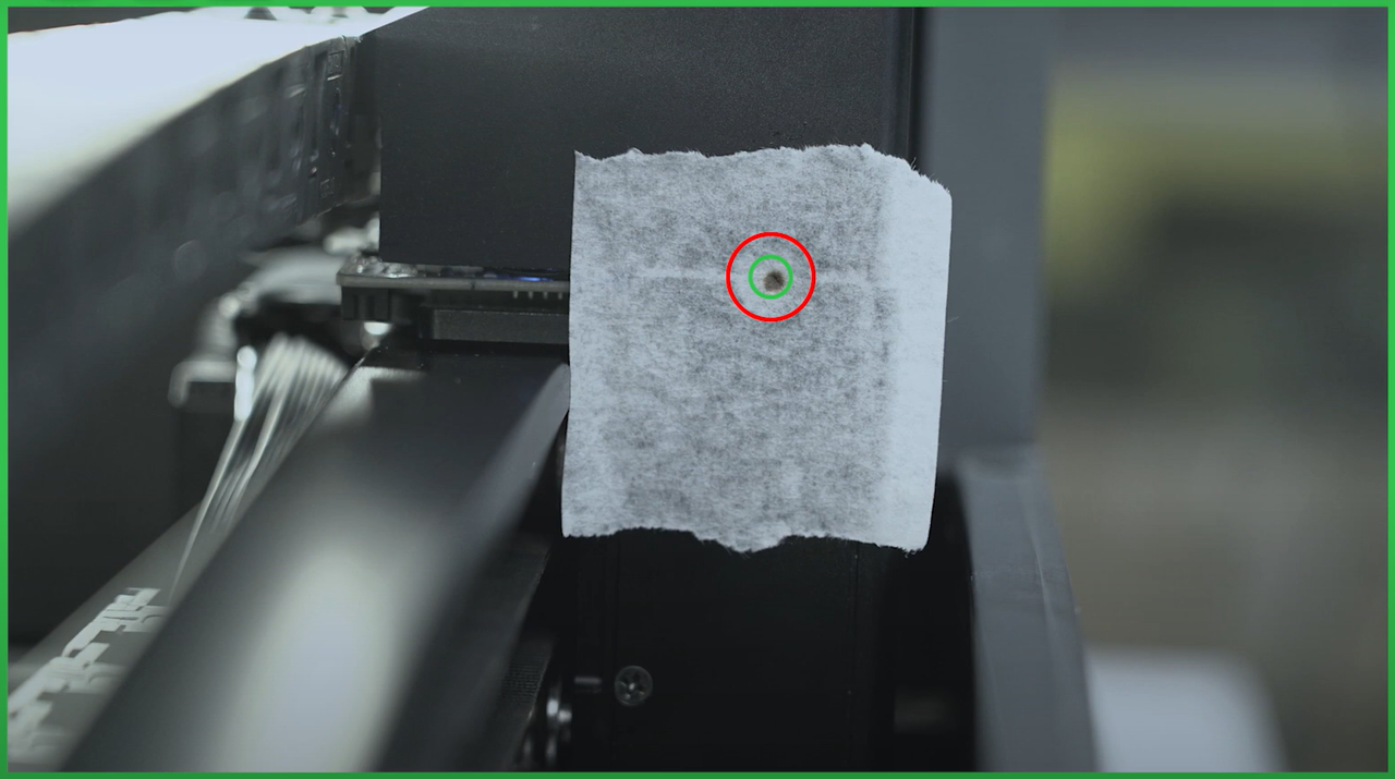
Please refer to the video to test the third optical path and determine if your machine needs calibration.
- If the burn mark is within the green circle, it means that no calibration is needed. As following picture shows:
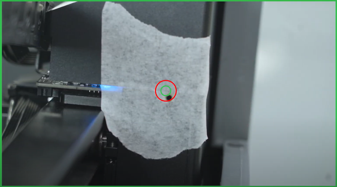
- If a burn mark appears but is outside the green circle or there is no mark on the tape (as following picture shows), follow the videos below to set up the optical path.
How to calibrate the optical path
Note: |
|---|
First optical path hole test
- This video guides you through testing the first optical path.
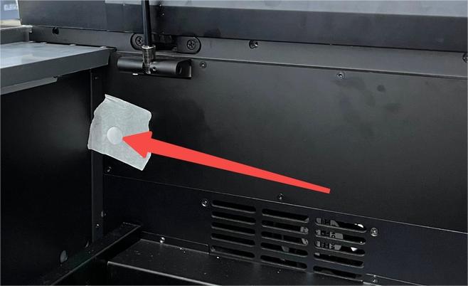
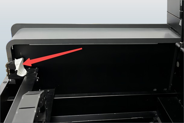
Stick the tape on the first optical path hole |
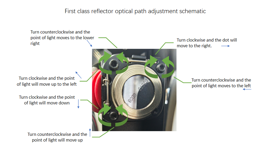
If the first optical path is tested not in the center, follow the steps to calibrate the first class reflector as illustrated.

Second optical path hole test and mirror calibration
- The video demonstrates how to test the second optical path and provides an example of calibrating it using one of the optical path offsets.
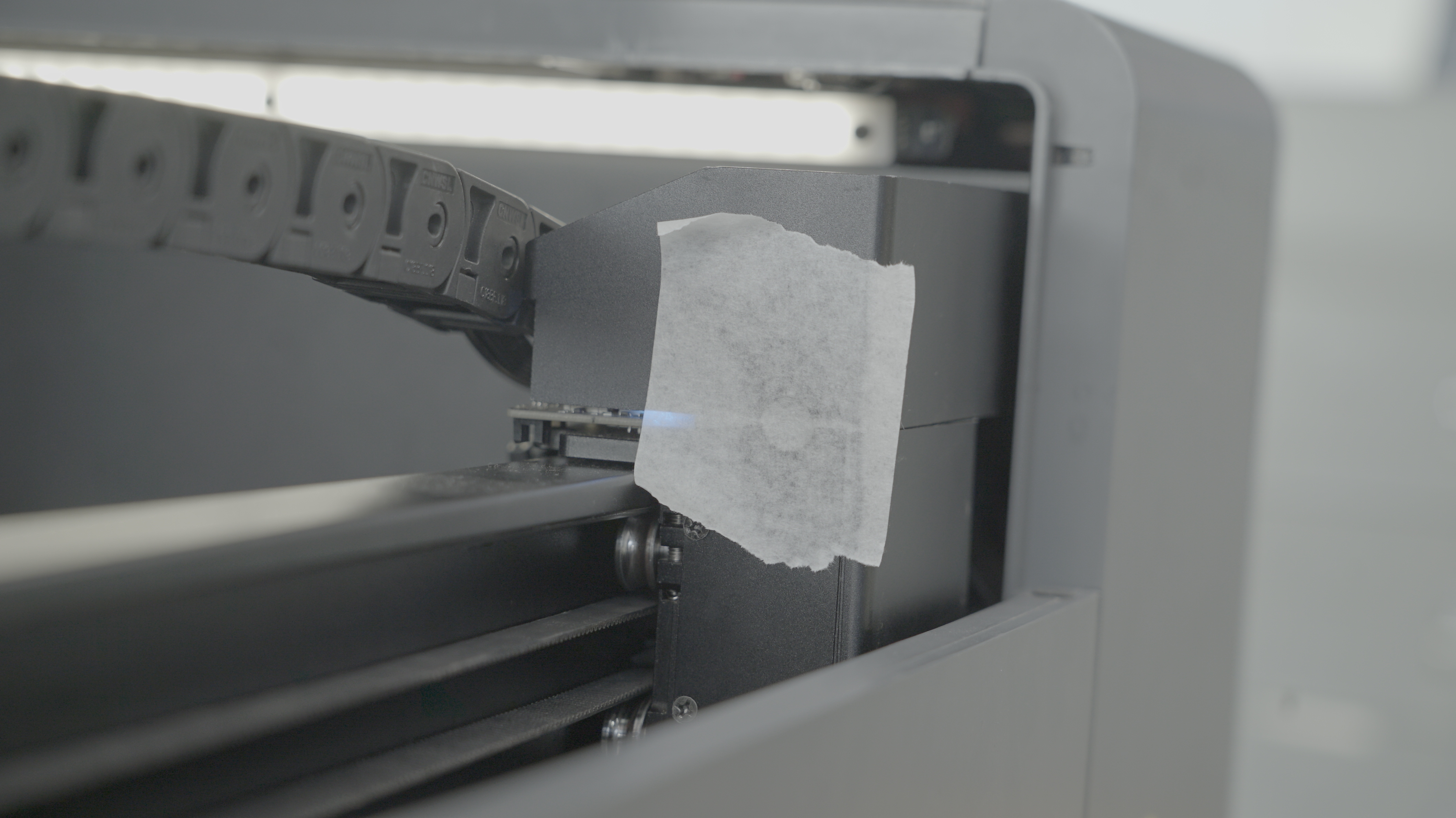
Stick the tape on the second optical path hole |
Calibrate the first mirror to guide the second optical path |
If the second optical path is tested not in the center, follow the steps to calibrate the first class reflector as illustrated.
Third optical path hole test and mirror calibration
- The video showcases the procedure for testing the third optical path and offers an instance of calibrating it with a major deviation where no mark is left on the tape.
Stick the tape on the third optical path hole |
Calibrate the second mirror to guide the third optical path |
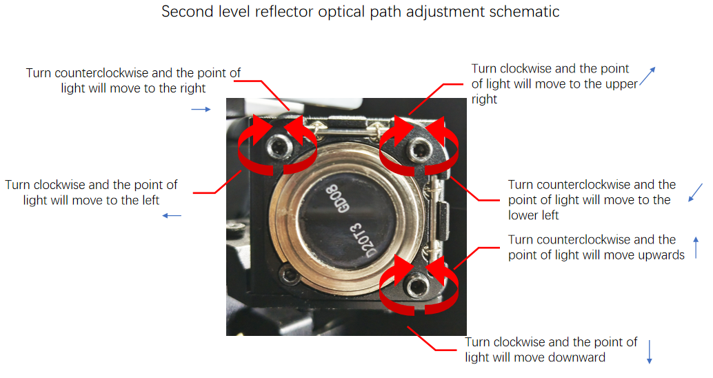
If the third optical path is tested not in the center, follow the steps to calibrate the second class reflector as illustrated.
FAQs
After adjusting the screws, you may experience either of the following:
There is still no change in the burn mark position.
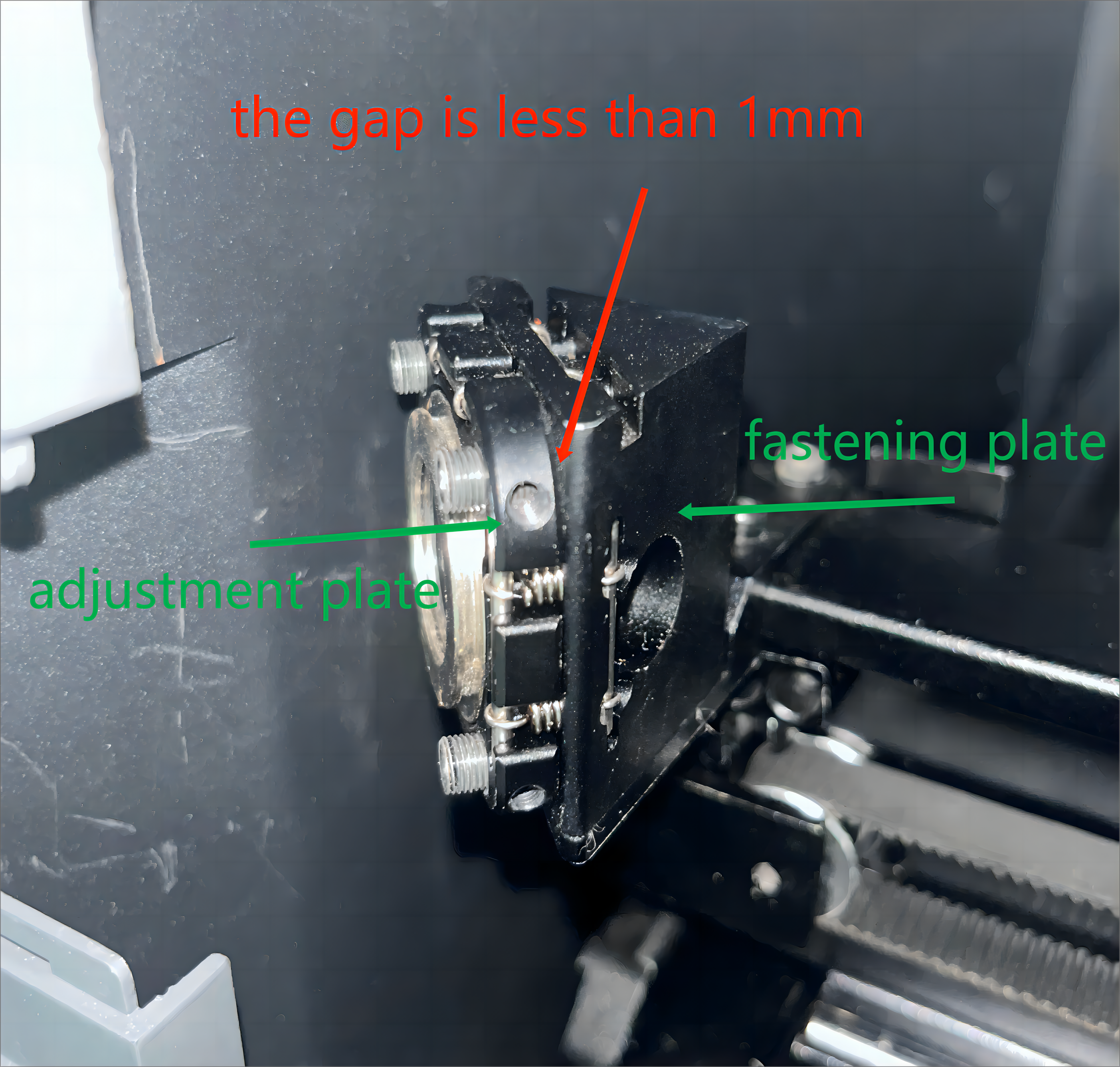
- If the burn mark doesn't change after adjustment, it could be due to a small gap between the adjustment plate and the fastening plate. This prevents the plate angle from changing, hindering optical path adjustment.
- Taking the third optical path mirror calibration as an example, if there's no change in the burn mark after adjusting the screws, check if the gap is less than 1mm between the adjustment plate and the fastening plate.
- If needed, widen the gap by turning the adjustment screws (as highlighted in yellow as shown in Pic 2) clockwise to ensure there's a 1mm gap between the two. This method applies to both the second and first mirror holders.
Pic 1 |
Pic 2 |

There is no mark appearing during the third optical path test
When the second optical path test is normal, no burn mark appears on the tape during the third optical path calibration with the laser module at the far left.
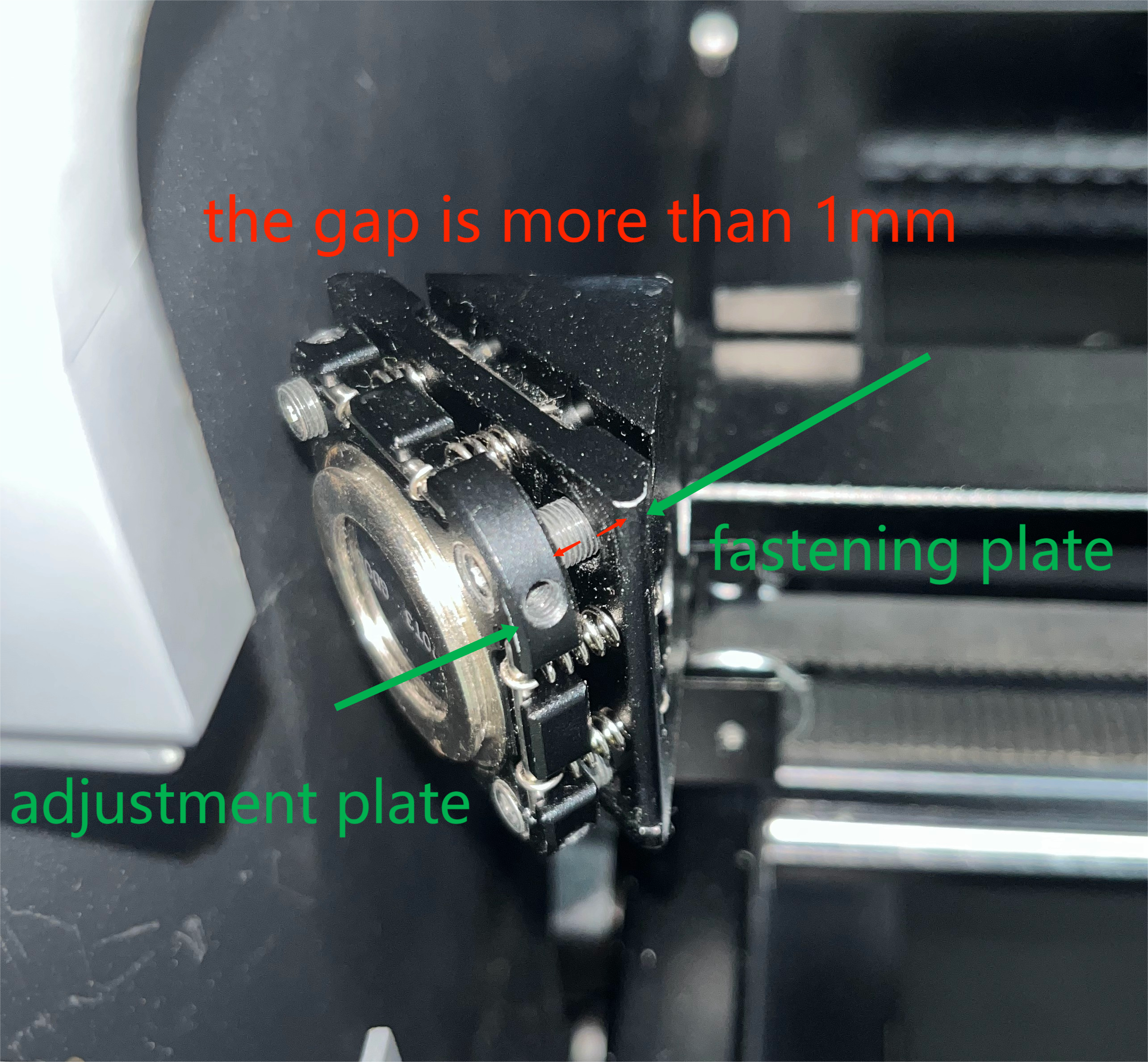
- Please check for excessive space between the adjustment plate and the fastening plate of the second mirror holder, as shown in Pic 3. If present, the laser's reflection angle may have changed, potentially causing it to hit the mirror holder's interior and blocking smooth reflection through the small hole in the holder.
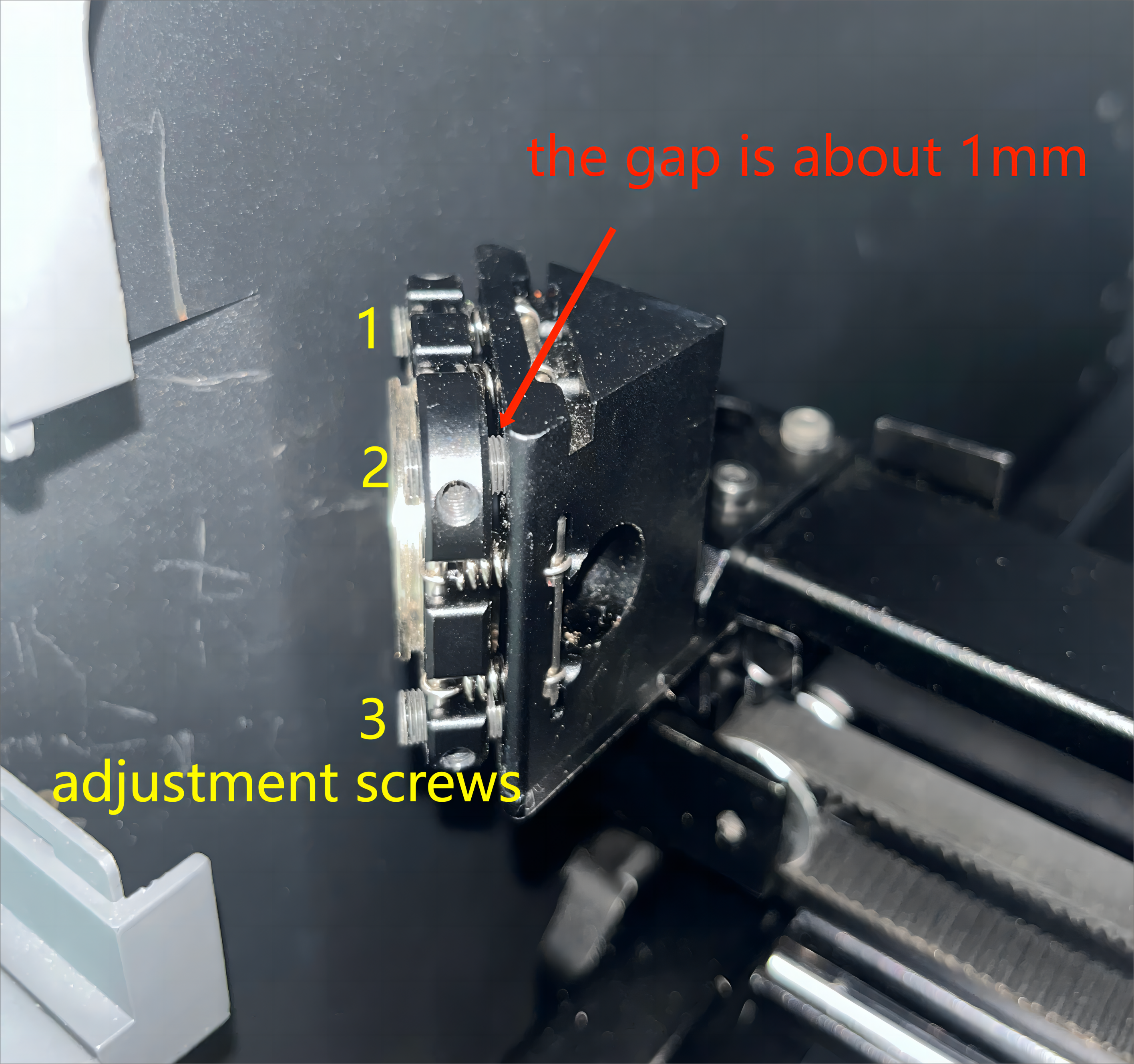
- Refer to the picture below to adjust the gap between the two to around 1mm (at the three locations marked in yellow in Pic 4). Turn the adjustment screws counterclockwise at the corresponding positions to reduce the gap.
- Once you have confirmed a 1mm gap at all three screw positions, you can proceed with further calibration of the optical path.
Pic 3 |
Pic 4 |
Help us improve
If this article or video doesn't effectively assist you in resolving the issue, please let us know by clicking the “No” button in the “Was this page helpful?” section below, and leave your feedback in the pop-up suggestion box. Our knowledge base team will review it and consider it for future updates.
Still need help?
If you need any human assistance, please create a ticket by clicking the “Submit a Ticket” button in the “Help Ticket” section below. Our service team will get back to you in 1 business day via E-mail.
