PDF files download
xTool D1 Pro Quick Start Guide-Part 1.pdf
xTool D1 Pro Quick Start Guide-Part 2.pdf
xTool D1 Pro Quick Start Guide-Part 3.pdf
Unbox and check
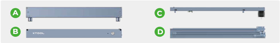
| Plate components A: Rear plate B: Front plate C: Left plate D: Right Plate E: Middle plate |
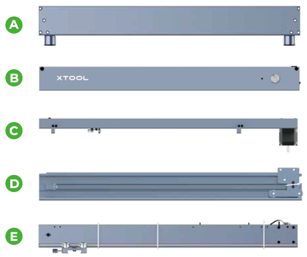
| Shaft |

|
|
|
|
Laser module | Safety goggles | Material pack | Quick Start Guide/ Instructions/Brochure |


|
|
|
|
|
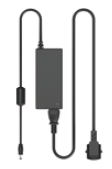
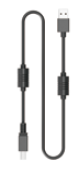
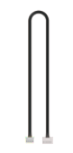
Power adapter & cable | USB cable | Motor cable | Cable tie pack | Limit switch connection cable |

|
|
|
|
|
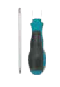
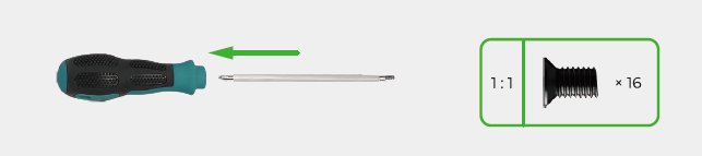
TF card | Coupling | Screwdriver | Hex key | |
|
|
|
| |
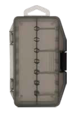
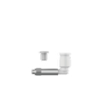
Parts storage box | Screw M4*8 | Screw M4*16 | Screw M4*25 | Nozzle connector components |


|
|
|
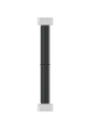
Aluminum sheet A4 |
|
|

Assemble xTool D1 Pro
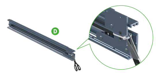
1. Fit the plates together
- Cut off the cable tie on the right plate. Note that no scissors are included in the pack.
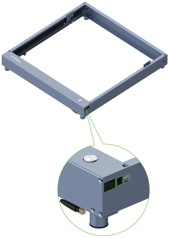
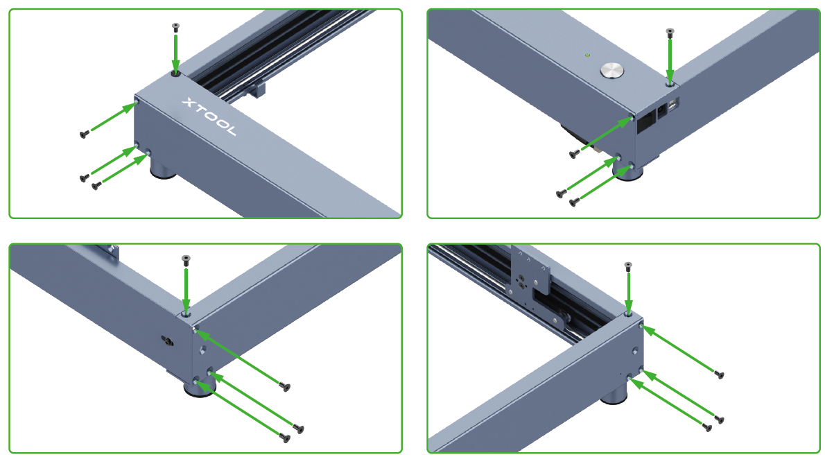
- Fit the four side plates together. Align the power switch, power port, and USB port with the openings on the right plate.
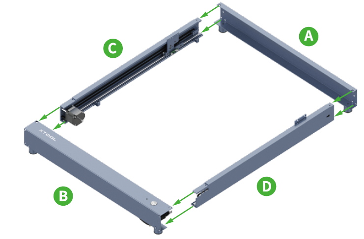
- Use screws to hold the side plates together.
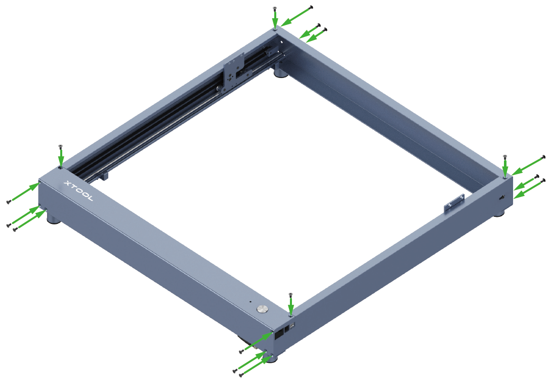
- Use screws to fit the timing pulleys.
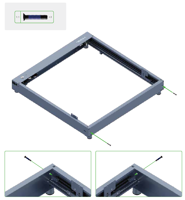
| The screws are used to set the tension of the timing belts. Do not fully tighten them. Otherwise, the timing belts may be damaged. |

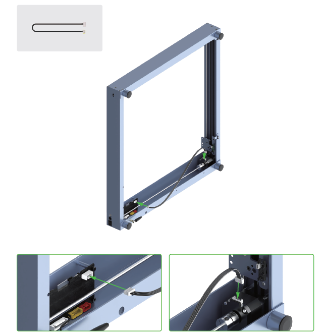
2. Fit the shaft
- Put the shaft through the coupling, and then put it through the timing belt and insert it into the idler pulley.
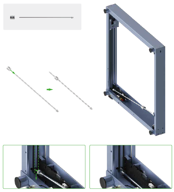
|
| If you can't put the shaft through the timing belt, the possible cause is that the timing belt is set too tight. You can adjust its tension by turning the screw. |

- Slide the coupling to the joint of the shaft and motor shaft.

Note: Keep a small distance between the coupling and motor, or the coupling can't rotate properly.
- Slide the two sliders down against the front plate.

- Fully tighten the two screws on the coupling.

3. Connect the motor on the left plate to the main control board
- Insert the connectors into the port on the main control board and the one on the motor, respectively.
|
| Pay attention to the front and back sides of the connector. Insert it properly. |

- Use cable ties to fix the motor cable on the front plate.

4. Fit the middle plate
- Cut off the white cable ties on the middle plate and reserve the black ones.

- Insert the connector of the motor cable into the port on the motor.

- Align the middle plate with the screw holes on the sliders, and use screws to hold the middle plate and sliders together.

- Use the screw to fit the timing pulley.

| The screw is used to set the tension of the timing belt. Do not fully tighten it. Otherwise, the timing belt may be damaged. |
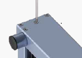
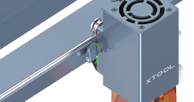
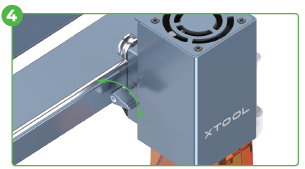
5. Complete the wiring
- Connect the limit switch component on the middle plate to the one on the slider of the left plate.
- Insert the connectors of the laser module, motor, and limit switch connection cables into the ports on the main control board, respectively.

- Use cable ties to fix the connection cables on the right plate.
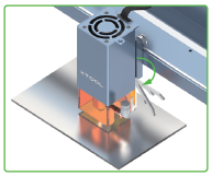
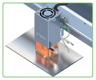
6. Install the laser module
- Install the nozzle connector and insert the plug.

- Connect the main control board and laser module.

- Fit the laser module on the middle plate.

- Use the thumb screw to fit the laser module.

|
|
|
Turn the handle clockwise | Hold the handle to draw it away from the thread part | Rotate the handle to stop it from being blocked |


|
|
Release the handle | Turn the handle clockwise again |

| You may need to repeat this process multiple times to tighten the thumb screw. |
| Use the thumb screw |

If the handle is blocked, you can tighten or loosen the screw as follows.
|
|
Hold the handle to draw it away from the threaded part. | Rotate the handle to stop it from being blocked The screw is not tightened or loosened. |
|
|
Release the handle The handle goes back to the default position. | Rotate the handle to tighten or loosen the screw |


7. Install the TF card

Great! The assembly is done.
Precaution
Prevent the middle plate and laser module from falling down themselves. Otherwise, the limit pieces may be damaged.

Meet your xTool D1 Pro

Set up xTool D1 Pro
Adjust the tension of the timing belts

| Try to set the timing belts on the right and left plates to the same tension, so that xTool D1 Pro can cut and engrave materials properly. |
Set the position of the laser module

|
|
|
Put the focal length setting bar down | Loosen the thumb screw on the other side and slide the laser module upward or downward | After determining the position, tighten the thumb screw and put the focal length setting bar back |

Set the position of the rear plate on the laser module
(Applicable only to the laser module of 20W)
| To cut thicker materials, you can adjust the position of the rear plate on the laser module, based on the scale with which the focal length setting bar is aligned, to ensure better cutting performance. |
It's recommended that you adjust the position of the rear plate according to the thickness of the material to be processed.
After adjusting the position of the rear plate, you can still use the focal length setting bar to set the position of the laser module.
Download and install software
You can operate xTool D1 Pro by using our official software xTool Creative Space (XCS) or the third-party software LightBurn.
Note: You need to purchase LightBurn before using it.

For details about how to use XCS to operate xTool D1 Pro, see "Operate xTool D1 Pro with XCS."
For details about how to use LightBurn to operate xTool D1 Pro, see "Operate xTool D1 Pro with LightBurn."
Create with example projects
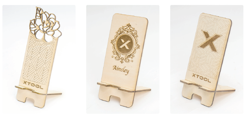
For details about how to create with example projects, see “Example Project - Making a Phone Holder.”
Before creating your works, you can place the aluminum sheet in the working area of xTool D1 Pro to protect your desk or floor from being smoked or burned.
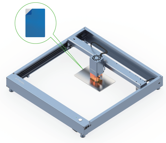
| If the aluminum sheet is not flat due to film removing, you can use masking tape to stick it on your desk or floor. |
Clean the laser module
When the light shield is dirty or laser beams can't cut a material, you need to clean the laser module.
|
|

- Remove the nozzle and its connector from the laser module.

- Clean the inner and outer frames of the light shield with tissues or dust-free cloth moistened with alcohol, and clean the laser lens and infrared laser-emitting point with a cotton swab moistened with alcohol.

