List of items
 |  |
 |
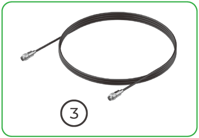
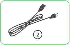
① xTool MetalFab CNC Cutter | ② Power cable | ③ Communication cable |
 |  |  |
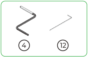
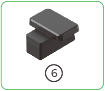
④ Z-shaped wrench | ⑤ External antenna | ⑥ Cable fixing block |
 |  |  |
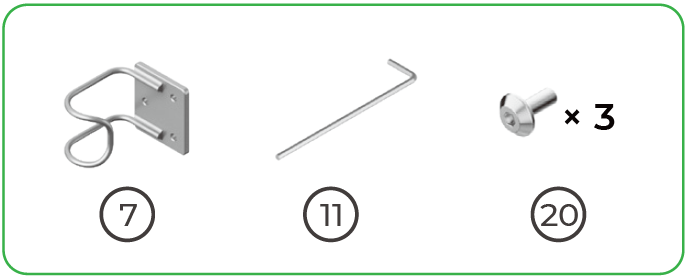
⑦ Hook | ⑧ Laser alignment card | ⑧ Red stamp pad |
 |  |
 |
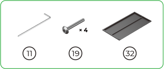
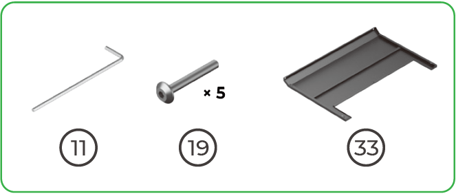
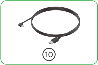
⑨ Level | ⑩ Computer connection cable | ⑪ Hex key 3 mm |
 |  |  |
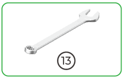
⑫ Hex key 4 mm | ⑬ Wrench | ⑭ Storage box |
 |  |  |
⑮ Cutting tip | ⑯ Cleaning nozzle | ⑰ Telescopic cutting nozzle |
 |  |  |
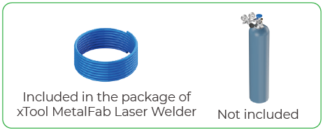
⑱ Ceramic ring | ⑲ Screw M4*30 | ⑳ Screw M4*10 |
 |  |
 |
㉑ Screw M6*12 | ㉒ Long fixing bar | ㉓ Short fixing bar |
 |  |  |
㉔ Camera calibration board | ㉕ Metal sheets | ㉖ Quick Start Guide |
 |  |  |
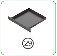
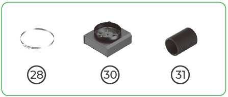
㉗ Safety Instructions | ㉘ Pipe clamp | ㉙ Baseplate |
 |  |  |
㉚ Exhaust fan | ㉛ Smoke exhaust pipe | ㉜ Front plate of the riser base |
 |  |  |
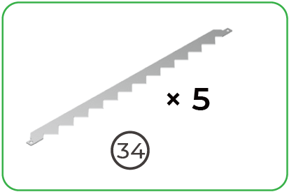
㉝ Back plate of the riser base | ㉞ Slat | ㉟ Side plates of the riser base |
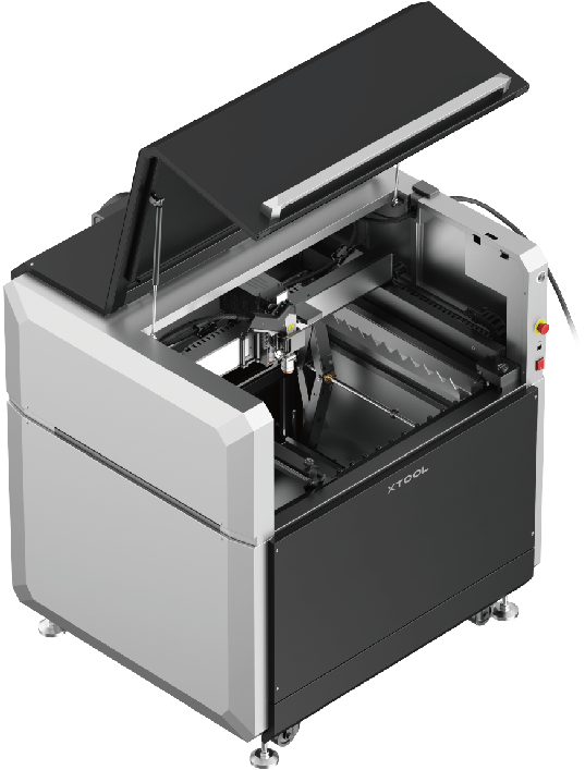
Meet xTool MetalFab CNC Cutter
Structure of the main unit


Annular indicator
Effect | Machine state |
Solid white |
|
Off | Sleeping |
Blinking blue slowly |
|
Solid blue |
|
Solid green | Processing done |
Blinking yellow slowly | Configuring network |
Solid purple | Upgrading |
Blinking red slowly | Abnormal |
Solid red | Emergency stop button pressed |
Buzzer
Effect | Machine state |
1 beep | Reminding users to operate |
3 consecutive beeps | Abnormal |
Specifications
| Product name | xTool MetalFab CNC Cutter |
| Dimensions | 1175mm × 1157mm × 749mm (W × D × H) |
| Dimensions (riser base included) | 1175mm × 1157mm × 1230mm (W × D × H) |
| Internal working area | 610 mm × 610 mm (W × D) |
| Maximum processing speed | 400 mm/s |
| Input power | Voltage range: 100 V to 240 V Full-load current: 2.5 A |
| Connection mode | USB, Wi-Fi, Ethernet port |
Preparation before assembling
Power
xTool MetalFab CNC Cutter requires 2.5 A, 100 V – 240 V single phase AC power.
As for xTool MetalFab Laser Welder, refer to its Quick Start Guide for power specifications.
Note:
■ Do not connect xTool MetalFab Laser Welder to a standard household circuit, as it may damage both the product and the circuit.
■ To ensure safety, it is recommended to install a 32 A air circuit breaker between the power supply and xTool MetalFab Laser Welder.
Shielding gas
The shielding gas should be dry, oil-free, and clean. Please prepare gas cylinders or gas generators that meet requirements.
Supported gas types
- Nitrogen
- Argon
- Oxygen
- Compressed air
The product does not come with a gas cylinder or gas generator. Please purchase one separately.
xTool MetalFab Laser Welder
- xTool MetalFab CNC Cutter needs to work with xTool MetalFab Laser Welder. During laser processing, xTool MetalFab Laser Welder is responsible for emitting laser, while xTool MetalFab CNC Cutter for controlling the processing.
- Since only the metal cutting function of xTool MetalFab Laser Welder is needed, it does not need to be assembled according to its own Quick Start Guide. If you have already assembled it, disconnect its power and remove unnecessary components.
Unbox and place the main unit
(1) Remove the items around the main unit in sequence.


(2) On the back of the main unit, tear open the black securing strap and unfasten it completely.

(3) Lift four leveling feet.
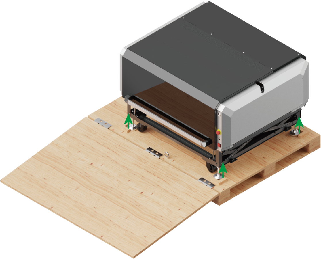
Note:
■ The top nuts are used to hold against the main unit baseplate.
■ The lower nuts are used to secure leveling feet.

| 
|
| 1. Use the wrench to turn the top nuts clockwise until they touch the lower nuts. | 2. Use the wrench to loosen the lower nuts counterclockwise. |
 |  |
| 3. Manually turn the leveling feet counterclockwise to lift them. | 4. The leveling feet should be about 1 cm above the limit blocks. |
(4) Move the machine to the desired position.
Note:
■ Reserve at least 1 m in front of the wooden box.
■ The machine will go downhill by inertia. Please control the moving speed.

Leave a clearance of at least 50 cm on all sides of the machine for subsequent assembly and operations.
![]()
Note: Cutting a material near the edges of the working area may cause sparks to splash out from the bottom of the device. Keep flammable materials, explosives, and solvents away from the device. Operators must stay at least 50 cm away from the spark-splashing zone.
(3) After moving the machine to the desired position, lower the leveling feet to secure the machine.
 |  |  |
| 1. Manually turn the leveling feet clockwise to lower them until they touch the ground. | 2. Use a wrench to tighten the lower nuts clockwise. | 3. Turn the top nuts counterclockwise until they touch the main unit baseplate and use a wrench to secure them. |
Assemble the riser base
Lift the main unit
(1) Use a 3 mm hex key to loosen the screws and take out the four fixing bars at the bottom corners.

Note: Sixteen M6*12 screws are taken out in this step. Please reserve them properly for subsequent use.
(2) At the back of the main unit, use a Z-shaped wrench to lift the main unit.

Get at eye level with the base beam to observe the white line. If the white line is level with the base beam, it indicates that the main unit has been lifted into the correct position.

Install the long fixing bars
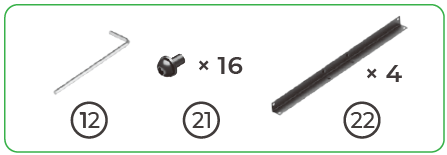
(1) Align the holes on the long fixing bars and the main unit.
If the holes fail to align with each other, please refer to the last step and use the Z-shaped wrench to adjust the height of the main unit.

(2) Use the hex key to screw in four screws to secure a long fixing bar in place. Do not tighten the screws yet.

(3) Secure the remaining three long fixing bars in the same way. Then, use the hex key to fully tighten all the screws on the four long fixing bars.

Install the short fixing bars
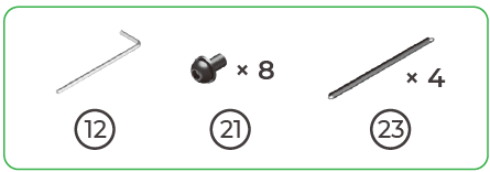
Attach the four short fixing bars to the front, left, and right sides of the machine.

Install the side plates
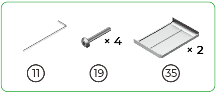
Note: The side plates are applicable to both the left and right sides.
(1) Align the slots in the side plate with the protrusions on the main unit.

(2) Gently push the side plate towards the main unit.

(3) Insert and tighten the screws.

(4) Install the other side plate in the same way.

Install the front plate
(1) Align the protrusions on the front plate with the slots in the main unit.

(2) Gently push the front plate towards the main unit.

(3) Insert and tighten the screws.

Install the back plate
(1) Align the slots in the back plate with the protrusions on the main unit.

(2) Gently push the back plate towards the main unit.

(3) Insert and tighten the screws.

Install the baseplate

Install the exhaust fan
(1) Attach the connector of the exhaust fan to that of the main unit.

Ensure that the side with arrows is facing up. Do not install it upside down.

(2) Align the four grooves of the exhaust fan with four fixing pins of the main unit and install the fan.

(3) Before snapping the exhaust fan into place, tuck the excess connecting wire into the hole of the exhaust fan.

(4) Then, gently press the fan down to make it fully seated.

(5) Loosen the pipe clamp.

(6) Stretch the exhaust pipe.

(7) Install the exhaust pipe to the exhaust fan.

(8) Fasten the pipe clamp.

Install the external antenna
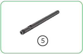
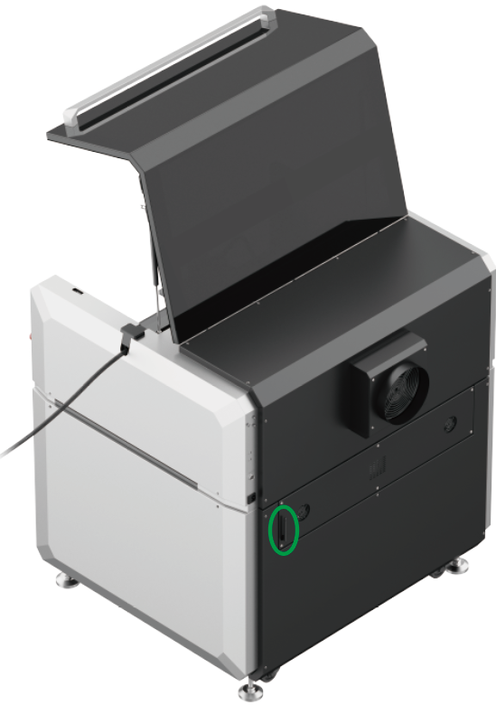
 |  |
| 1. Install the external antenna into the slot of the main unit. | 2. Rotate the antenna clockwise. |
 |  |
| 3. Raise the end of the antenna. | Done! |
Install the welding head
Connect to xTool MetalFab Laser Welder
Before connection, ensure that neither of the two machines is connected to the power supply.

Prepare to secure the welding head
(1) Rotate the three wing bolts counterclockwise to take them out.

(2) Move the carriage to the center.

(3) Open the toggle latch.

Install the cutting tip
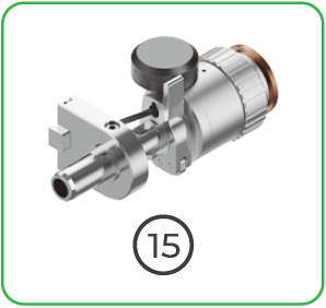
(1) Take out the welding head from the xTool MetalFab Laser Welder.

(2) Replace the welding tip with the cutting tip.

Secure the welding head
(1) Straighten the welding head cable. Ensure that the welding head does not hit the ground.

(2) Loop the welding head cable around the back of the carriage.

(3) Align the two grooves on the side of the welding head with the two fixing pins of the carriage.

If you can't snap the welding head into place, please check if the cutting tip is correctly installed.
(4) Close the toggle latch.

(5) Secure the three fixing rings on the welding head cable to the corresponding slots inside the machine.

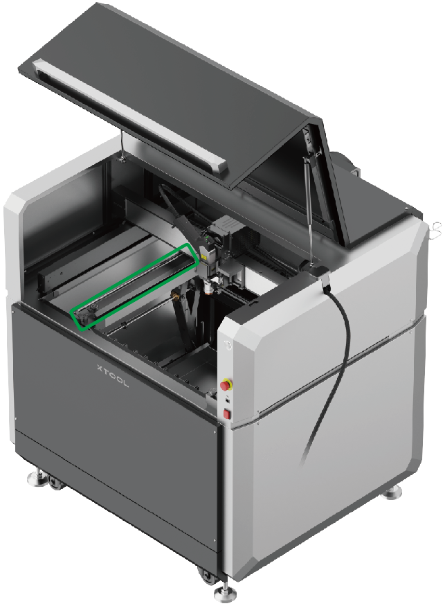
(6) Snap the cable into the clamp.

Ensure that the cable is fixed in place and doesn't touch the x-axis guide rail.

(7) Use the cable fixing block to secure the fixing ring in the right slot of the machine.

Before use
Connect to a power supply
(1) Connect xTool MetalFab CNC Cutter to a power supply.

(2) Rotate to unscrew the dust cap from the power connector, insert the power cable and rotate to secure it. Connect the other end of the power cable to a circuit that meets requirements.

■ Do not connect the product to a standard household circuit, as it may damage both the product and the circuit.
■ Wiring operations should be performed by a professional electrician.
■ For more details, see xTool MetalFab Laser Welder's Quick Start Guide.
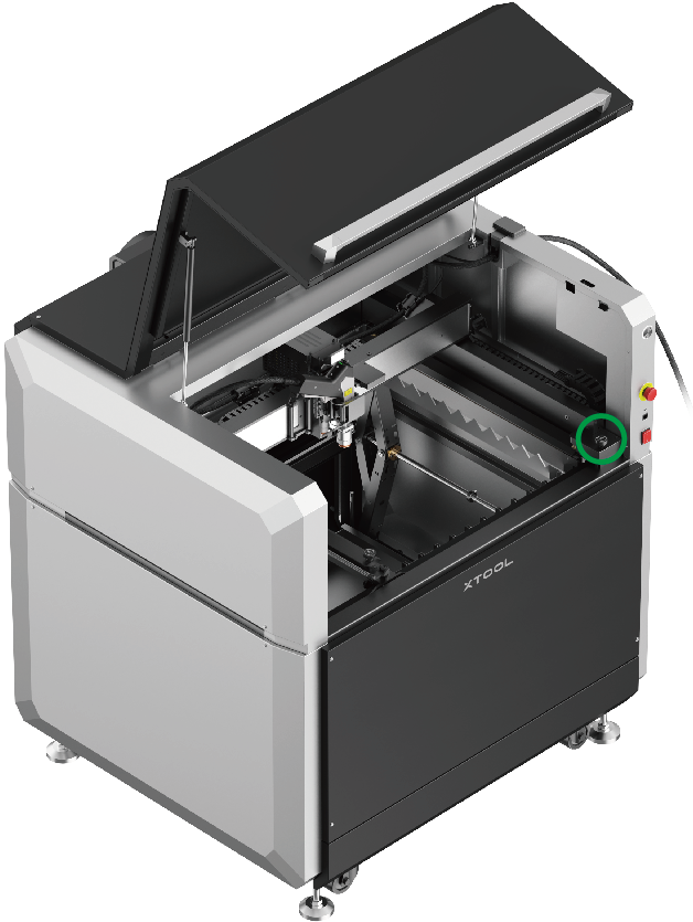
Check the emergency stop button
Ensure that the emergency stop buttons of the two machines are released. If they are pressed, rotate to release them.

Emergency stop button
■ If an emergency occurs, press any of the emergency stop buttons to shut off the corresponding device.

■ After dealing with the emergency, rotate the emergency stop button to release it.
Insert the key
Insert the key into its designated port of xTool MetalFab Laser Welder.

You can use the key either as an access-control key or a remote interlock connector.
Access-control key
Removing the key can disable the machine's processing and related functions.
Remote interlock connector
For detailed instructions, visit support.xtool.com/article/1367.
Power on
Press the power switches to turn on the two machines.
 |  |
| 1. Turn on xTool MetalFab CNC Cutter | 2. Turn on xTool MetalFab Laser Welder |
Connect the gas cylinder
(1) Insert one end of the tube into the shielding gas inlet on xTool MetalFab Laser Welder.

To learn more about the structure and detailed operations of the welding machine, please refer to the Quick Start Guide of xTool MetalFab Laser Welder.
(2) Connect the other end to the gas cylinder, or air compressor and air dryer. Then, open the valve according to the instructions for the cylinder or devices.

Place a material

Scenario 1: Place a thick material
 | |
| 1. Place a slat with its teeth facing up and its ends fitting snugly into two slots in the working area. | |
 |  |
| 2. Place slats with one slot apart. Decide the number of slats to be placed as required. | 3. Place a material on the slats. |
Scenario 2: Place a thin material
 1. Rotate the right fixture knob counterclockwise. |  2. Insert the right side of the material into the right fixture. |  3. Rotate the knob clockwise to tighten the right fixture. |
 |  |  |
| 4. Rotate the left fixture knob counterclockwise. | 5. Lift the linkage lever. | 6. Move the left fixture to the right. |
 |  |  |
| 7. Insert the left side of the material into the left fixture. | 8. Rotate the knob clockwise to tighten the left fixture. | 9. Lower the linkage lever. |
Scenario 3: Place a large material
(1) Install the hook onto the main unit.

(2) Hang the cable on the hook at the back of the device.

(3) Rotate the right knob on the main unit to release the right clamp.

(4) Rotate the left knob on the main unit to release the right clamp, then raise the level.

Note: You're advised to place slats for support before feeding the material.
(5) Insert the material into the main unit through its side slots.

(6) Rotate the left knob on the main unit and lower the level.

(7) Rotate the right knob on the main unit.

Use xTool MetalFab CNC Cutter
Get xTool software
(1) Visit s.xtool.com/software to get xTool software.

(2) Connect xTool MetalFab CNC Cutter to your computer with the USB cable. Then, open xTool software and connect the product.

Popular operations
Cutting with lead-ins

Before cutting, the laser pierces the material from the outside or inside of the target design. Then, starting from this point, the laser cuts the material following the cutting trajectory, avoiding incomplete cutting or uneven cutting surfaces.
Fly cutting

When the shapes to be cut are regular shapes (such as rectangles and circles) and arranged in a certain pattern, fly cutting can cut these shapes in the same direction altogether to increase cutting speed and save processing time.
Auto nesting

xTool software supports automatic nesting of objects to be processed, so as to make full use of materials.
For more information on how to use the unmentioned accessories and operate xTool MetalFab CNC Cutter with software, visit support.xtool.com/product/55.
Maintenance
Replace the lens protector in the welding head
(1) Remove the cover on the top of the welding head.

(2) Remove the lens protector closer to the nozzle.

After the lens protector is removed, it is recommended that you put the cover back to prevent dust from falling inside the welding head and causing damage.

(3) Use a tweezer or other tools to remove the gasket and lens protector.

(4) Install a new lens protector.
Do not touch the glass with your fingers or other tools during replacement as the glass may get dirty. If the glass accidentally gets dirty or dusty, use a cotton swab to clean it.
Remove the protective film on the top

Remove the other protective film

Services & Help
Learn & Community
Contact Us

Copyright © 2025 xTool All Rights Reserved.