Connect xTool S1 to XCS
xTool Creative Space (XCS) is an all-in-one software for graphic designing and editing, laser process setting, and machine controlling.
Minimum and recommended PC requirements
Item | Minimum configuration | Recommended configuration |
Processor | Intel Core i5-6200U | Intel Core i5-11600 |
Operating system | Win 10 (64 bit) macOS 10.14 or later | |
RAM | 8 GB | 16 GB |
Display resolution | 1280 × 720 (pixels) | 1920 × 1080 (pixels) or higher |
Hard drive | 8 GB | 12 GB |
- With the minimum configurations, all the functions of XCS can be used properly. When you import a complex image, such as an image larger than 50,000,000 pixels or an SVG image larger than 1 MB, however, XCS may fail to run smoothly.
- With the recommended configurations, XCS can run more smoothly when you import and edit a complex image, the software delay may be shorter, and the performance is better.
Download and install XCS
(1) Download the software XCS from https://www.xtool.com/pages/software.
(2) Double-click the software you've downloaded to install it.
.png)
Note: Click Yes if you are asked "Do you want to allow this app to make changes to your device?" and then continue the installation as prompted.
(3) Open XCS. On the top-right corner, click the  icon > Settings, and set the display language for XCS.


Connect xTool S1 to XCS
(1) Use the USB cable to connect xTool S1 to your computer.

Note: If the provided USB cable is incompatible with your computer, you need to use an adapter, which is not included in the pack.
(2) Open XCS on your computer. On the top-right corner of XCS, click the + New project button.

(3) On the right side of the project editing page, click Connect device.

Note: If you have connected an xTool device in XCS before, click the  icon > Connect device.
(4) On the pop-up window, click the name of your device to connect to it.
.png)
Note: After the device is connected, you can configure Wi-Fi for the device. This way, you can connect xTool S1 to XCS through Wi-Fi next time.
Set up xTool S1 in XCS
(1) In the top-right corner of XCS, click the gear icon next to the xTool S1 image to open the device setting window.

(2) In the Basic info tab, you can view the basic information of xTool S1 and make modifications to some information if needed.

- Device name: Set a new name for your xTool S1.
- Firmware version: Check for updates and update the firmware if a new version is available.
- Wi-Fi setting: Connect your xTool S1 to a Wi-Fi network.
(3) In the Working info tab, you can set up the device and export files or logs as needed.

- Flame alarm: If a flame is detected, xTool S1 will pause processing and raise the alarm.
- Stops when moved: If xTool S1 is moved or tilted during processing, it will pause processing.
- Lens protector cleaning reminder: If this feature is turned on, XCS will remind you to clean the lens protector at a proper interval.
- Fill light brightness: Adjust the brightness of the fill light in the working area.
- *Auto-adjustment for the air assist set:
If you connect xTool S1 with the air assist set (updated version), you can turn on Auto-adjustment for the air assist set.
Set the airflow levels respectively for engraving and cutting. The airflow increases from 1 to 4, and 0 means no airflow. During processing, XCS adjusts the airflow based on your setting.
Note 1: For an air assist set that is not of the updated version, you cannot set Auto-adjustment for the air assist set for it.
Note 2: You are advised to use a small airflow for engraving and a large airflow for cutting.
- Exhaust fan: Turn on the exhaust fan, and the fan will work to exhaust smoke during processing.
- Exhaust time after processing:
If the exhaust fan is turned on, you can set the duration at which the exhaust fan continues to work after xTool S1 stops processing. By setting this parameter, you can make the exhaust fan work longer to absorb the remaining smoke.
- Buzzer reminders: Turn on the buzzer reminders, and the buzzer will make sounds in situations such as when the device is ready for processing, the processing is completed, and so on.
- *Time the purifier continues to work:
If you connect xTool S1 with the smoke purifier, you can set the duration at which the smoke purifier continues to work after xTool S1 stops processing. By setting this parameter, you can make the smoke purifier work longer to absorb the remaining smoke.
- *Use conveyor feeder (Convey the material back after processing):
If you connect xTool S1 with the automatic conveyor feeder, you can turn on Convey the material back after processing.
After xTool S1 finishes processing, the conveyer feeder will transfer the material back to its original position.
- Higher x-axis acceleration: If higher x-axis acceleration is turned on, xTool S1 will use a higher acceleration to reach the speed set for processing.
The supported processing modes
XCS that runs on the computer supports the following processing modes:
- Process on baseplate: Process materials with flat and smooth surfaces with the baseplate in place
- Use rotary attachment: Use xTool S1 with the rotary attachment to process cylindrical and spherical materials, including irregular ones
- Curved material: Process materials with curved and smooth surfaces
- Use conveyor feeder: Use xTool S1 with the conveyor feeder to process long materials
- Screen preparation: This mode is developed for xTool Screen Printer, used to engrave screens for printing.
Process materials with flat surfaces
Notes
xTool S1 supports different material thicknesses when working with different accessories.
Combinations of xTool S1 and accessories | Supported material thickness (H) |
xTool S1 | 0 mm < H ≤ 42 mm |
xTool S1 + slats | 0 mm < H ≤ 34 mm |
xTool S1 + honeycomb panel | 0 mm < H ≤ 15 mm |
xTool S1 + riser base | 70 mm ≤ H ≤ 125 mm |
xTool S1 + riser base + honeycomb panel | 0 mm < H ≤ 99 mm |
xTool S1 + riser base supporting conveyor feeder | 15.5 mm ≤ H ≤ 133.5 mm |
xTool S1 + riser base supporting conveyor feeder + honeycomb panel | 0 mm < H ≤ 106.5 mm |
1. Place the material
Open the lid of xTool S1, and place the material to be processed on the baseplate.
.png)
Note: To cut a material, you are advised to place the slats or honeycomb panel on the baseplate before placing the material. The slats or honeycomb panel can reduce the burned area on the back of the material and protect the baseplate..png)
2. Open or create a project
You can open a project to start processing or create a new project. If you create a new project, you need to design patterns and set parameters from scratch.
- Open a project
On the home screen of XCS, click Open from computer. In the pop-up window, select a file of the xTool Creative Space Project (. xcs) type and click Open.
Note: The project file can contain information such as processing patterns, processing modes, and processing parameters. However, if the machine model, processing mode, or material thickness used in the project varies from the current situation, you need to reset the corresponding parameters.
- Create a new project
On the home screen of XCS, click + New project.
3. Select the processing mode and material name
(1) On the top of XCS, click the name of the current processing mode, and then select Process on baseplate as the processing mode.

(2) In the top-right corner, click User-defined material, select the name of your material, and click Confirm.

Note:
- If you can't find your material in the list, you can click More xTool materials to search among more materials in the Material EasySet Library.
- If you still can't find the name of your material, you can select User-defined material.
Note: After you select a material from the material list or Material EasySet Library, the software will automatically set parameters for laser processing. The default settings apply to xTool materials. You can adjust the settings based on your needs.
(3) Turn on or off Laser module position based on your need.
Note: If you turn on Laser module position, XCS will display the position of the laser module in real time. The red cross in the canvas indicates the laser module, and the coordinates of the laser module are shown near Laser module position.

4. Set the laser focus
xTool S1 has a distance sensor, which can measure the distance between the laser module and the material surface. You can also manually measure and calculate the distance between the laser module and the material surface, and input the obtained values into XCS.
During processing, xTool S1 will perform auto-focusing based on the Distance parameter.
- Auto measure
(1) Move the laser module over the material. Ensure that the locating spot falls on the surface of the material.

(2) In the top-right corner of XCS, click the Auto-measure icon  , and xTool S1 will automatically measure the distance from the laser module to the material surface.

Note: Before auto-measure, ensure that the probe of the distance sensor is not extending.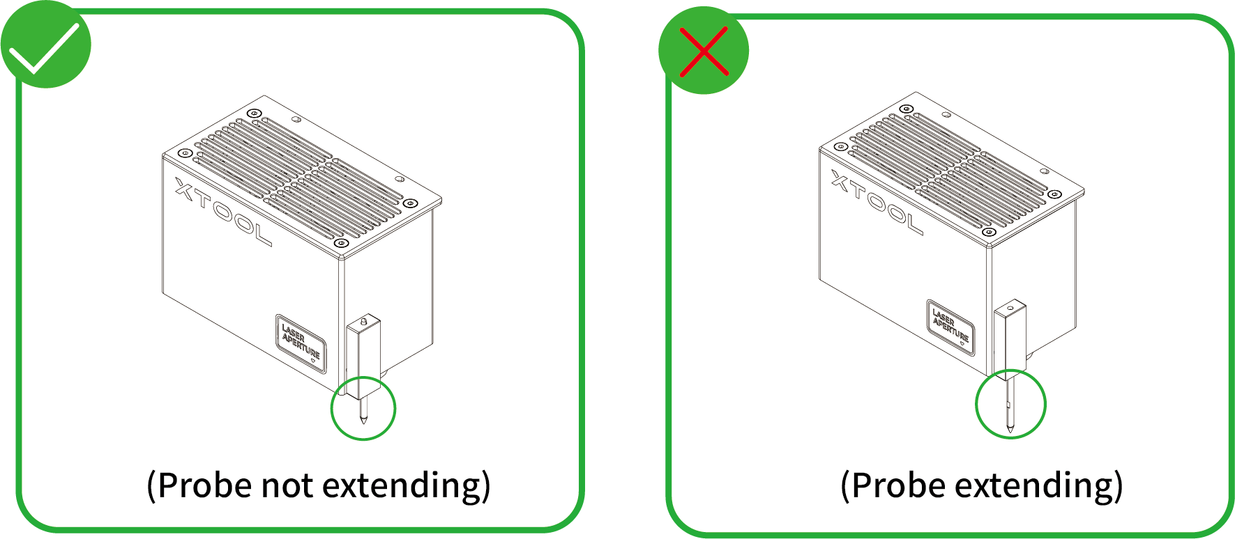
- Manual measure
(1) Use a ruler to measure the distance from the surface of the material to the top of the laser module.

(2) Subtract 100 mm (3.937 inches) from the measured value from step (1), and input the calculated value as Distance in the top-right corner of XCS.

5. Mark the target processing area on the canvas
(1) In the top-right corner of XCS, click the Mark processing area icon  .
.

(2) Select a marking mode based on the shape of the target processing area, and click Start marking.
(Here the Rectangle mode is used as an example.)

(3) Manually move the laser module to make the red cross fall at a vertex of the target processing area, and press the button on the device to record the position. Then, repeat the same steps to record the other required vertex(es) of the target processing area.

(4) Click End marking > Done, and then the target processing area will be marked out on the canvas.


6. Design objects for processing
Note: The target processing area is marked out by a black perimeter as a rectangle. You can design objects within this area.
(1) Use the tools to the left side of the canvas to create objects. You can import images, insert shapes, enter text, or draw vector graphics.

Note: XCS supports importing the following image formats: SVG, DXF, JPG, JPEG, PNG, BMP, etc.
(2) Select the objects to further edit them using the tools above the canvas.

7. Set parameters for processing
Select objects on the canvas first. On the right side of XCS, set parameters for the selected objects.

Note:
You need to set parameters for every object. A missed object may fail to be processed.
The parameters that can be set for bitmap objects and vector objects are different. You can select multiple objects of the same type and set parameters for them at once.
8. Preview the processing area
You can preview the processing area on the material by framing. Framing means laser dots walk along the border of the processing objects on the material. Take the following steps to start framing:
(1) In the bottom-right corner of the software, click the  icon next to the Framing button to set the speed for framing.

Note: You can click the arrow buttons to control the movement of the laser module. The other three parameters allow you to configure how the laser module moves with every tap on an arrow button.
XY speed (mm/s): The moving speed of the laser module in X and Y directions.
XY distance (mm): The moving distance of the laser module with each tap on an XY arrow button.
Z distance (mm): The moving distance of the laser module with each tap on a Z arrow button.
(2) Close the lid of xTool S1, and then click Framing in the software. Press the button on xTool S1 to start framing. The laser spot will move along the boundary of the processing pattern on the material so that you can preview the processing area.

(3) After you confirm that the processing area is proper, click Framing completed in XCS. If the area is not ideal, you can adjust the material position or adjust the element positions in the software, and then preview the processing area again.

9. Start processing
(1) In the bottom-right corner of the software, click Go to process.

(2) Preview the processing pattern and path.
On the bottom-left corner, click the  button, and XCS will show you the processing path.

(3) In the upper-right corner of XCS, click Start.

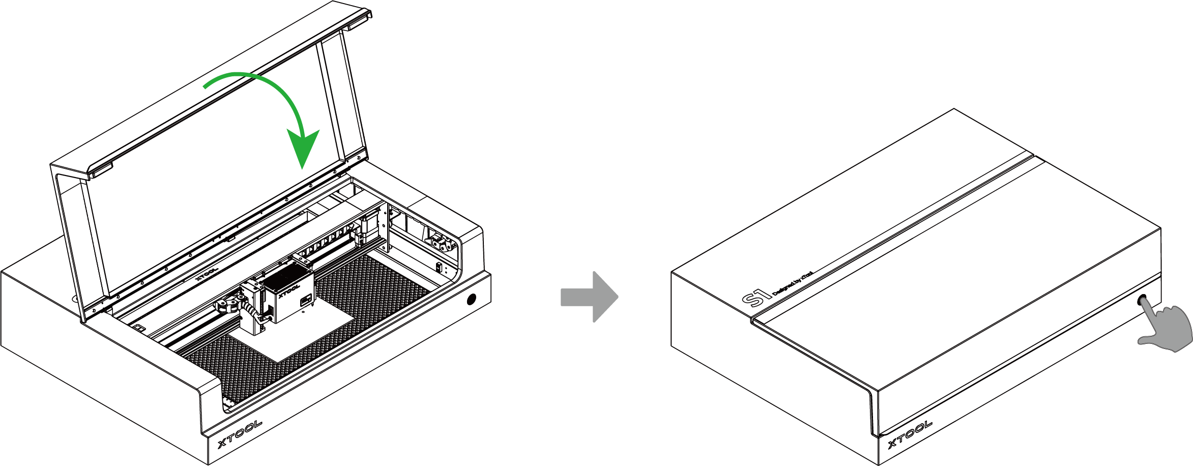
(4) Close the lid of xTool S1. Then, press the button on xTool S1 to start processing.
Process materials with curved surfaces
Notes
- Supported material thickness
xTool S1 supports different material thicknesses when working with different accessories. To process a material with curved surfaces, ensure that the overall height of the material does not exceed the supported material thickness.
Combinations of xTool S1 and accessories | Supported material thickness (H) |
xTool S1 | 0 mm < H ≤ 42 mm |
xTool S1 + slats | 0 mm < H ≤ 34 mm |
xTool S1 + honeycomb panel | 0 mm < H ≤ 15 mm |
xTool S1 + riser base | 70 mm ≤ H ≤ 125 mm |
xTool S1 + riser base + honeycomb panel | 0 mm < H ≤ 99 mm |
xTool S1 + riser base supporting conveyor feeder | 15.5 mm ≤ H ≤ 133.5 mm |
xTool S1 + riser base supporting conveyor feeder + honeycomb panel | 0 mm < H ≤ 106.5 mm |
- Supported curve
Please use a material with a smooth surface and gentle curves. Ensure that the angle between the tangent to the curve at any point and a horizontal line is no more than 15 degrees.

- Software requirement
Only XCS that runs on the computer supports the Laser curve mode. XCS that runs on mobile phones or iPads does not support the Laser curve mode.
1. Place the material
Open the lid of xTool S1, and place the material to be processed on the baseplate.

Note: When measuring the curved surface, the distance sensor touches the material surface by its probe. To ensure the stability of the material, you can use other objects to secure or support the material.
2. Open or create a project
You can open a project to start processing or create a new project. If you create a new project, you need to design patterns and set parameters from scratch.
- Open a project
On the home screen of XCS, click Open from computer. In the pop-up window, select a file of the xTool Creative Space Project (. xcs) type and click Open.
Note: The project file can contain information such as processing patterns, processing modes, and processing parameters. However, if the machine model, processing mode, or material thickness used in the project varies from the current situation, you need to reset the corresponding parameters.
- Create a new project
On the home screen of XCS, click + New project.
3. Select the processing mode
(1) On the top of XCS, click the name of the current processing mode, and then select Curved material.

(2) Turn on or off Laser module position based on your need.
Note: If you turn on Laser module position, XCS will display the position of the laser module in real time. The red cross in the canvas indicates the laser module, and the coordinates of the laser module are shown near Laser module position.
4. Select the target processing area
(1) On the top of XCS, click the  icon > Curve-measure.

(2) Move the laser module until the locating spot falls on the vertex in the top-left corner of the target processing area. Click Mark to mark it as vertex 1.
Tip: You can manually move the laser module or click the arrow buttons on the software to move the laser module. If you use software control, you can set the distance the laser module moves with each click of the arrow button through Distance.

(3) Move the laser module again until the locating spot falls on the vertex in the bottom-right corner of the target processing area. Click Mark to mark it as vertex 2.

(4) After you finish marking the two vertices, click Next.

5. Set the measurement density
(1) XCS provides recommended measurement density based on the size of the marked area. You can adjust the measurement density as needed.
Tip: The more rows and columns, the higher the measurement density, the more precise the model, and the longer the measurement time.

(2) Click Start measuring, and the laser module will measure the height of each point on the selected surface. You can see the measurement progress on XCS.

(3) After the measurement is complete, XCS generates a model.
- You can rotate and view the model by dragging it with the mouse.
- You can also adjust the Smoothness and Tension of the model to make it closer to the actual object.

(4) Click Done. The selected and measured area is displayed normally on the canvas, while the other area becomes grey.


6. Design objects for processing
Note: The gray area on the canvas is an unmeasured area. Do not place processing elements in this area.
(1) Use the tools to the left side of the canvas to create objects. You can import images, insert shapes, enter text, or draw vector graphics.

Note: XCS supports importing the following image formats: SVG, DXF, JPG, JPEG, PNG, BMP, etc.
(2) Select the objects to further edit them using the tools above the canvas.

7. Set parameters for processing
Select objects on the canvas. On the right side of XCS, set parameters for the selected objects.

Note:
You need to set parameters for every object. A missed object may fail to be processed.
The parameters that can be set for bitmap objects and vector objects are different. You can select multiple objects of the same type and set parameters for them at once.
8. Preview the processing area
You can preview the processing area on the material by framing. Framing means laser dots walk along the border of the processing objects on the material. Take the following steps to start framing:
(1) In the bottom-right corner of the software, click the icon next to the Framing button to set the speed for framing.

Note: You can tap the arrow buttons to control the movement of the laser module. The other three parameters allow you to configure how the laser module moves with every tap on an arrow button.
XY speed (mm/s): The moving speed of the laser module in X and Y directions.
XY distance (mm): The moving distance of the laser module with each click on an XY arrow button.
Z distance (mm): The moving distance of the laser module with each click on a Z arrow button.
(2) Close the lid of xTool S1, and then click Framing in the software. Press the button on xTool S1 to start framing. The laser spot will move along the boundary of the processing pattern on the material, so that you can preview the processing area.
(3) After you confirm that the processing area is proper, click Framing completed in XCS. If the area is not ideal, you can adjust the material position or adjust the element positions in the software, and then preview the processing area again.

9. Start processing
(1) In the bottom-right corner of the software, click Go to process.

(2) Preview the processing pattern and path.
On the bottom-left corner, click the button, and XCS will show you the processing path.

(3) In the upper-right corner of XCS, click Start.

(4) Close the lid of xTool S1. Then, press the button on xTool S1 to start processing.

Services & Help
Learn & Community
Contact Us

Copyright © 2025 xTool All Rights Reserved.